Follow along with the video below to see how to install our site as a web app on your home screen.
Note: This feature may not be available in some browsers.
Welcome to ASR. There are many reviews of audio hardware and expert members to help answer your questions.
Click here to have your audio equipment measured for free!
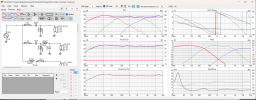
Do you think the tweeter phase could be negligible? Does the crossover seem well done in general? I'm a novice, I think I did everything correctly, but maybe I'm wrong.
Do you think the tweeter phase could be negligible? Does the crossover seem well done in general? I'm a novice, I think I did everything correctly, but maybe I'm wrong.
Looks like a decent start but will second the need for off-axis measures to really determine. Not sure why you would want resistor in series with the woofer and is a rather large inductor on it. The tweeter looks a little hot so might want to attenuate it more.
Where did you get your measurements from? Did you trace these or measure in box?
Series resistors on woofers should be avoided (unless these form part of a notch filter). that is the woofer sets the overall system sensitivity. If you are having to use a series resistor, then I'd increase the series inductor or parallel cap to achieve the desired slope. We don't want to waste precious woofer sensitivity in resistance. Besides, this series resistor will see a lot of power (100w+) so you'd need to size it appropriately (or parallel many higher value / lower power resistors). Hence why we avoid such designs.