• WANTED: Happy members who like to discuss audio and other topics related to our interest. Desire to learn and share knowledge of science required. There are many reviews of audio hardware and expert members to help answer your questions. Click here to have your audio equipment measured for free!

Where does quantization noise come from.

solderdude

Grand Contributor
Joined
Jul 21, 2018
Messages
16,128
Likes
36,702
Location
The Neitherlands
Yup - appreciate all that. I'm not worried if it's audible or not, I'm talking theoretically here. I just don't understand why quantizing is creating "noise" when in my head it's just modifying the original signal.
That modification is in small and high frequency range and is basically noise. No signal is no quantization noise.

What is constructing the red noise line in Monty's chart? The only thing that knows about the quantization error is the ADC, so how does it ever appear in the DAC?
It appears in the DAC because it only 'knows' the values of the samples. Not what is in between them.
In NOS R2R DAC's there are actual stair-steps with substantial quantization crap (noise) that is not filtered at all.
In OS R2R DACs there are smaller errors (noise) because intermediate samples are calculated (filters) and frequency of that noise is higher up as the steps are smaller and shorter.
In those DACs there actually is noise that is determined by the frequencies present and amplitudes.
There usually is a post filter that filters out the ultra-high frequencies but lower frequencies (most of them above the audible range) are still there.

DSvsNOSR2R.jpg.webp


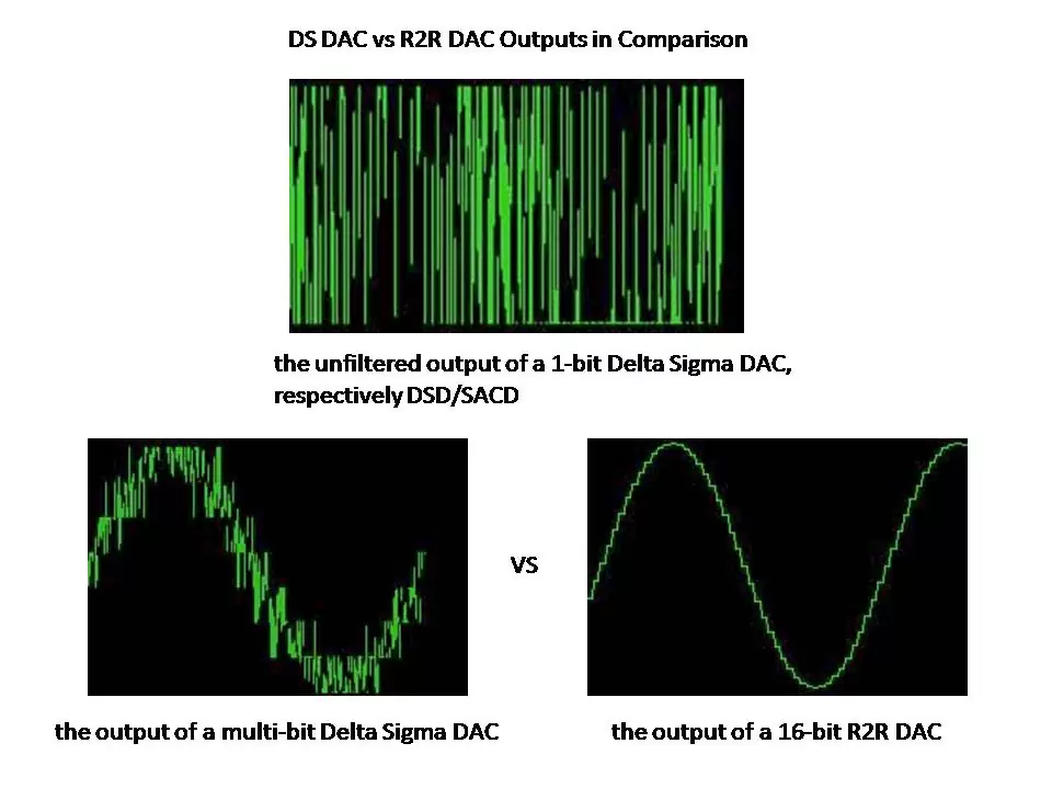
With DS there are just a few bits (4 to 7) and by calculation the actual intended sample value (and all calculate in-between values) are obtained by an 'average' of the few actual bit values it toggles between (at a very, very high frequency). This creates a lot of noise, high in amplitude (coarse bit values) and very high frequency.
That noise is 'shaped' and most of it is above the audible range.
The ultra-high frequency crap is easily filtered with a simple post filter which prevents MHz crap to be at the analog out.
The left bottom scope shot is what is coming out of a DS DAC before the highest frequencies are filtered out by the post filter. Thus you end up with a 'clean' signal which still has a very small amount of noise in it created by quantization errors of the 'just a few bit' DAC. Most of it well above the audible range.
 
Last edited:

AnalogSteph

Major Contributor
Joined
Nov 6, 2018
Messages
3,412
Likes
3,363
Location
.de
Which I guess then begs the question, how do we know if the signal contains noise or is in fact what it was supposed to sound like in the first place?!
That'll be easier to tell with some signals (e.g. a sine wave) than with others. If in doubt, an input/output comparison is going to be required.

The DAC is oblivious to all this. It just interpolates between the sample values it's given with its anti-imaging filter.

If quantization noise itself is giving you a hard time, wait till you learn how we get rid of it - dithering. Well, get rid of it actually isn't the right expression, what's there is just being randomized to the point of being indistinguishable from good ol' analog noise. The total quantity of noise actually increases, but as it becomes entirely uncorrelated to the signal you can dig almost arbitrarily deep into the noise floor with ever narrower filtering and still recover more signal. Even for signals with a peak-peak amplitude much smaller than one LSB, which unaided would be merely recorded as all-zero and consequently be lost.

There are some funny ways of generating dithering noise for an ADC. The Sony PCM1630 made use of a dedicated digital random noise generator IC with its output attenuated to the desired level, while more consumer-focused DAT recorders went with the more low-tech version of basically attenuating everything to microphone level first, introducing just enough noise to provide adequate dithering to their 16-bit ADCs in the process. (Which is a valid approach but obviously makes the signal a tad sensitive to other kinds of unwanted interference. That may have been seen as a bit of a challenge in the PCM1630, a pro-level device stuffed with a bunch of circuit boards and all kinds of digital and analog electronics.)

The challenge of overcoming a gross nonlinearity is actually much older than digital audio, first presenting itself in magnetic tape (and wire) recording. The solution there was what enabled high fidelity audio recording in the first place: High-frequency AC bias. You can see dither as a relative of that. (Same goes for the 1-bit to a few bit converters with delta-sigma modulation that are everywhere these days.)
 

Mulder

Addicted to Fun and Learning
Forum Donor
Joined
Sep 2, 2020
Messages
645
Likes
895
Location
Gothenburg, Sweden
Qquantization noise is hard to understand intuitively, but a very good question, because it has often been portrayed in the HiFi world that quantization gives rise to a choppy stair step curve, which is much less perfect than the smooth precise analog audio curve. The problem with this is that this choppiness appears to be intuitively graspable and this seems to explain the hard and cold sterile digital sound compared to smoth analog sound. Explaining why this conclusion is wrong is not entirely easy, because it appears counterintuitive and requires some mathematical understanding. In addition, Amazon and Tidal and other streaming services, as well as other players in the HiFi market, happily spread the image of the stair step sound. So the initial question of where the quantization noise comes from is in my view a very good question. I have not seen any intuitively graspable explanation illustrating why quantization noise occurs.
 

wwenze

Major Contributor
Joined
May 22, 2018
Messages
1,341
Likes
1,905
Not entirely wrong since the stair steps are the cause of the noise, and if you save and reproduce a 24-bit instead of 16-bit wave the steps are smaller and the noise lower.

We just don't call it distortion despite knowing the contributing factors, because the contributing factors themselves are also random distributed.

I have not seen any intuitively graspable explanation illustrating why quantization noise occurs.

Can be exemplified in decision making. Is 2.5 rounded to 3 or 2? Sometimes you think it is 3, sometimes 2. If you're lucky you get an average of 2.5 and many samples of 2 and 3, if you're unlucky you round everything up to 3. Dithering is when you add random noise so you get 2.49 and 2.51 so it helps you make the decision to get the average closer to 2.5
 

Mulder

Addicted to Fun and Learning
Forum Donor
Joined
Sep 2, 2020
Messages
645
Likes
895
Location
Gothenburg, Sweden
Not entirely wrong since the stair steps are the cause of the noise, and if you save and reproduce a 24-bit instead of 16-bit wave the steps are smaller and the noise
You are completely missing my point. The stair step curve is in some places incorrectly described as a graphically correct image of the actual sound curve. So my post is not about the step curve per se, but about what it is falsely claimed to represent.
 

MaxwellsEq

Major Contributor
Joined
Aug 18, 2020
Messages
1,780
Likes
2,705
Another thing that might be confusing is in the analogue world we are used to "noise" that is random or incoherent (such as the "woosh" or "hiss" from a detuned radio). But noise is effectively "unwanted" added stuff, and when we think of mains hum (a single frequency) as noise, it helps a bit.

The thing about quantisation noise is that is not truly random or incoherent, but is an artefact of the ADC having to pick a value when the signal is between two fixed levels. Therefore, with absolutely no input quantisation noise is effectively zero, whereas with analogue tape the noise is at a relatively constant level, regardless of input signal.
 

DonH56

Master Contributor
Technical Expert
Forum Donor
Joined
Mar 15, 2016
Messages
7,918
Likes
16,721
Location
Monument, CO
It's the difference between the actual signal and the quantized (digital) value. This article might help:

The "stair steps" should never appear in the final DAC output due to the anti-image filter that removes high-frequency content beyond Nyquist (see e.g. https://www.audiosciencereview.com/...ital-audio-converters-dacs-fundamentals.1927/ ).
 

Tell

Active Member
Joined
Mar 30, 2024
Messages
129
Likes
168
Quantization noise happens when you try to quantize (=digitize) a waveform.

It happens because the original waveform may have a value of t1=4.43 but your digitizer is only capable of t1=4 or t1=5.

That error, happening thousands of times per second, results in quantization noise.

You don't have to have the original waveform to compare against, to objectively identify quantization noise as noise, because the noise is correlated to the input signal, and our brains are very good at picking out such noise.

We can mask that correlated noise by injecting uncorrelated noise, which is much easier for the brain to ignore.

An analogy would be aliasing artefacts in digital photography:
View attachment 364674

Super irritating, very identifiable even without a reference to compare to, and professionals get rid of it by injecting uncorrelated noise in form of an OLPF.
Your explanation is of course correct, except your analogy with aliasing in digital photography doesn't work since that's directly comparable to aliasing in audio :)
Instead this example below is better. To the left is a gradient and in the middle is the same gradient but in 2 bits, so four shades of grey, and to the right is the same 2 bits but with noise added before removing all those bits we had from the start.

blender_240423-002202.png
 

pablolie

Major Contributor
Forum Donor
Joined
Jul 8, 2021
Messages
2,134
Likes
3,617
Location
bay area, ca
Yup - appreciate all that. I'm not worried if it's audible or not, I'm talking theoretically here. I just don't understand why quantizing is creating "noise" when in my head it's just modifying the original signal. What is constructing the red noise line in Monty's chart? The only thing that knows about the quantization error is the ADC, so how does it ever appear in the DAC?

I did say there is a fundamental part of the process I'm not "getting"!
The "reconstruction" is based on a Fourier transformation. In math the transformation is perfect (Nyquist theorem), in practical implementations a meaningless amount of what you call "noise" may remain. Not sure I entirely trust that graph though.
 

kemmler3D

Major Contributor
Forum Donor
Joined
Aug 25, 2022
Messages
3,461
Likes
7,077
Location
San Francisco
There have been some good explanations in this thread.

What made quantization noise click for me was understanding that, at the ADC, the difference between the original signal and the digitized signal is basically random. Every time you sample the original signal, you represent that signal with the number that is closest to the real value, but there is almost always a small discrepancy. The size of the discrepancy is random.

And so in a sense, you can consider the digital signal to be the original signal plus a random value for each sample. And what do we call a random, rapidly changing addition to our signal? Noise!

NB: Quantization noise goes down when you add more bits, because you have 2x more numbers to choose from for each bit you have available.
 

pablolie

Major Contributor
Forum Donor
Joined
Jul 8, 2021
Messages
2,134
Likes
3,617
Location
bay area, ca
...

NB: Quantization noise goes down when you add more bits, because you have 2x more numbers to choose from for each bit you have available.

All true. One thing to keep in mind with Fourier transformations is that, once you have done a few of them, you learn that the differences in the permutations on [n] decrease exponentially, very rapidly. People obsess about minute differences that don't interfere with our ability to direct space flights or missiles etc. If you think your hearing requires more resolution that the ability to land a moon probe within 5 inches 240k miles away, hey, good for you. :)
 

tmtomh

Major Contributor
Forum Donor
Joined
Aug 14, 2018
Messages
2,815
Likes
8,281
OK - this may be due to lack of sleep or I'm just being incredibly stupid and missing the obvious - but I can't get my brain around where the noise comes from!

View attachment 364662
So this is an image from the famous Monty video - and basically everything he says makes perfect sense.

I appreciate the red line is the difference between the original and the quantized signal - but surely the DAC has no knowledge of the original signal?
In my head, the DAC is reading t1=4, t2=5, t3=6, t4=5, t5=2, t6=-1, ... and constructs the only continuous path to join the dots and creates the the yellow line.

So the analogue signal out the DAC is the yellow line. It doesn't know the green line at all - so where is the red line in the output!? In my head we just have 2 waveforms, the input and the output which are just very slightly different!

I think to think I'm pretty intelligent and have a pure maths degree, so I'm wondering why I'm finding this so hard to understand!!!

I think this is a really good question, and a fascinating one at that!

As I see it, you've asked three main questions and two of them have been pretty thoroughly answered by others' helpful and astute comments:

1. How do we know what the red line is - in other words, how can we accurately measure/map the quantization noise? The easiest way to think about it is that the quantization noise is not usually directly observed or heard. It's derived by subtracting the yellow line's values from the green line's values (or vice-versa - doesn't really matter for purposes of determining the average magnitude of the noise).

2. Where is the noise in the yellow line? isn't the yellow line just a signal rather than being the green signal plus noise? When we're talking about properly generated output using 16-bit or 24-bit formats, the answer is that for practical purposes Yes, the yellow line is just a signal and the noise is "nowhere" in the sense that we don't hear it. Of course it's possible to hear the noise: take a 16-bit source, put on headphones, and during the silence between songs, crank up the volume all the way - you might hear it (although you still might not if the source was produced with noise-shaping dither). But in the overwhelming majority of situations we don't hear quantization noise.

3. How do we ever know what the green line is exactly? Audio isn't like that photo where we can see the flaws. This, I think, is the one question to which you haven't necessarily gotten a complete answer.

One way of addressing this is to say, as has been noted already, that we can generate simple signals where the voltages can be measured fairly easily and we can show definitively that the voltage values cannot be perfectly encoded in a digital sampling system with finite bit depth. (This can also be proven mathematically, but this would be a practical example where it could also be directly measured.)

Another way of addressing this is to go back to Monty's video where you got your original screenshot. The beauty of digital sampling is that we don't need to know or "see" the green line - the original signal - because as Monty says, digital sampling can reproduce the original signal perfectly, except with quantization noise. He demonstrates this by reducing the bit depth to 8 bits (and if memory serves maybe even to 6 or 4, I don't recall at the moment) - and you can still hear the original signal, just with more noise.

So it doesn't matter what the green line is, as long as our yellow line contains the full range of audible frequencies that were in the green line, and as long as the yellow line doesn't have audible noise. With a 16-bit, 44.1kHz sample rate system with noise-shaping dither and a well-chosen reconstruction filter, that's the case. In other words, we don't need to care what the green line looks like - we only need to have a system that we know can create a yellow line with sufficient frequency response capability, sufficiently low noise floor, and good rejection of out of band frequencies with minimal aliasing.
 
Last edited:

wwenze

Major Contributor
Joined
May 22, 2018
Messages
1,341
Likes
1,905
Just FYI, depends on what you meant by everything and perfect sense...

He didn't mention that the DAC he used was doing internal upsampling.

If he tested with a non-oversampling (NOS) DAC, he would get a very different result. More info NOS DAC. Non-Oversampling DAC [Advantages, Disadvantages] (samplerateconverter.com)

For any video like this, I would not just take his claims as fact; I would do my own independent checking to verify what he said. As most of the time, the fact may surprise you.

This is what you would get from the audio output of a modern DAC (Topping E30) with a perfect digitized 1kHz sine wave input (under the "NOS" mode):

View attachment 365371

For a perfect 10kHz sine wave, it's look would be even more interesting (under the "NOS" mode):

View attachment 365372
Source: How to pick the best filter setting for your DAC – Addicted To Audio

In my mind, I would not just simply trust these video (especially with the so-called "expert") without futher checking. I would consider what he said is just "another set of data point" for my thinking (as he does indeed provide good input at least for me to further study). Remember, expert is like you and me but they may just have a bit more experience in certain area. I don't believe they have a very special super brain.

The LPF of these DACs just happen to be at a way higher frequency, while the interpolation magic in between is supposed to be done by the oversampling (or digital filter) and then the resulting smaller steps would be eaten up by the LPF.

Doing this gives us the option of more complex digital filters that the user can select. Or even the option to turn it off. Again, not completely off, since the analogue section wouldn't be bypassed (I hope?), but good enough to see the steps.

If you selected a NOS DAC with a LPF of a low enough frequency you would not see the steps. In any case, a LPF at 20kHz anywhere in the signal chain would maim the steps.

And the difference between the maimed sinewave and the steps leads us back to the thread topic.
 
Last edited:

voodooless

Grand Contributor
Forum Donor
Joined
Jun 16, 2020
Messages
10,433
Likes
18,446
Location
Netherlands
So the analogue signal out the DAC is the yellow line. It doesn't know the green line at all - so where is the red line in the output!? In my head we just have 2 waveforms, the input and the output which are just very slightly different!

I think to think I'm pretty intelligent and have a pure maths degree, so I'm wondering why I'm finding this so hard to understand!!!
See it this way: if you failed your math test, and you don’t know why, it doesn’t change the fact that you failed your test ;)
 

Chromatischism

Major Contributor
Forum Donor
Joined
Jun 5, 2020
Messages
4,833
Likes
3,765
Yup - appreciate all that. I'm not worried if it's audible or not, I'm talking theoretically here. I just don't understand why quantizing is creating "noise" when in my head it's just modifying the original signal. What is constructing the red noise line in Monty's chart? The only thing that knows about the quantization error is the ADC, so how does it ever appear in the DAC?

I did say there is a fundamental part of the process I'm not "getting"!
Maybe it's an issue of terminology not fitting the phenomena well.

I think of it more as quantization "error" rather than "noise".
 

solderdude

Grand Contributor
Joined
Jul 21, 2018
Messages
16,128
Likes
36,702
Location
The Neitherlands
Looks to me the middle shows more than 2 bits. It shows 4 boxes of gradients. Am I correct?
2 bits has 4 values (gradients):
00
01
10
11

4bits has 16 values (gradients):
0000
0001
0010
0011
0100
0101
0110
0111
1000
1001
1010
1011
1100
1101
1110
1111

For the more complex digital filters, did you mean do it externally outside the DAC?
Digital filters are before the DAC section and require upsampling and interpolation making the steps shorter in duration and because of interpolation smaller in steps.
The higher the new samplerate the smaller the 'steps' will be. It is very easy to build a post-filter that is not steep (complex) which will then filter (smooth) the small steps that remain and make it a smooth analog signal. This is how oversampling DACs work.

DS DACs with NOS setting only emulate a sample-hold (filterless) R2R DAC output hence you can measure/see stairsteps even with non R2R DACs.

Analog post filters are extremely difficult to make and will have post ringing only.
Only the first gen CDP (aside from Philips) had a steep analog reconstruction filter which was possible because there was only one samplerate (44.1kHz)
This is technically not feasible with DACs that must switch sample rate. Of course one could make a steep 20kHz filter but in that case it would be pointless to support higher samplerates.
 
Last edited:

solderdude

Grand Contributor
Joined
Jul 21, 2018
Messages
16,128
Likes
36,702
Location
The Neitherlands
yes the optical illusion is caused by also seeing the gradients on both sides.
Just cover the left and right gradient and the illusion is gone.
If only we could just as easily remove sonic illusions, that would have saved a lot of bytes (typed characters) in the usual threads where people hear things that (most likely) aren't real.... pesky brain is always in the way.
 

Andreas007

Active Member
Joined
Mar 11, 2019
Messages
147
Likes
390
Location
Germany, Bavaria
Wow! Very quick turn from technical topic into philosophical discussion about reality… :oops:
Please continue with technical part, it was most interesting.
 

wwenze

Major Contributor
Joined
May 22, 2018
Messages
1,341
Likes
1,905
For the more complex digital filters, did you mean do it externally outside the DAC?
It's part of the oversampling DAC's feature already. ES9038 has 7 presets to choose from.

Taking the 10kHz square wave for example, instead of taking just an analogue filter with low LPF frequency to smooth it into some arbitrarily sine-ish wave, an oversampling DAC with digital filter keeps the square wave (as much as the downstream LPF stage allows anyway), cuts up the square wave into many pieces horizontally, then creates a new curve based on black magic.


MaxwellsEq

Major Contributor
Joined
Aug 18, 2020
Messages
1,780
Likes
2,705
No, I am wrong. They are the same :eek:. I got tricked by this visual illusion. :facepalm:
Finally :D

You are also being tricked by your brain audibly as well.
 
Top Bottom