KT-80 mods to lighting and regulator have now been completed. It's never as easy as you think it is (e.g. getting the power supply board in and out is a really fiddly affair as clearance is super-duper tight and the wires are a bit stubborn; you better get some Menthos for the
hare's breath), but the good news is that all of them work just about exactly as simulation said they would.
1. Lighting
a) Part 1 - Power supply work
Old D24 was pretty toast, as suspected. Once removed, multimeter reading parallel to bulb went into the
megohms. (Stubborn little fella, wouldn't readily come out.)
Old C90 actually still tested quite alright. (C = 1005 nF, ESR = 6.5 Ω, Vloss = 1.7%)
R111, as toasty as it ran, still measured 177 ohms.
Not all heroes wear capes.
D24 was swapped for new small 8V2 (BZX23 series) installed a few mm above board height. (According to sim, Pd = 0.06 W with LED bulb replacement installed or 0.1 W without. It's a nominal 0.6 W part.)
Added rectifier diode Dnew (1N4002) was installed below, its parallel capacitor Cnew above the board.
R111's remaining legs were bent until they could be soldered to my 22.5 mm 3.3µ/100V laying down.
Result: 8.138 Vdc and a steady green dial pointer LED.
b) Part 2 - Power indicator LED mod
The dead bulb could be pushed out of the silicone holder thingy and cut off. Holder thingy ultimately was not reused and the cable now comes in from the left and above with the LED at the end pointing towards the responsible lightpipe area. Warm-white LED turned out to be one sans integrated resistor after all, so I found two 2k2s in my stock which were used in parallel. Heatshrink of various diameters was used. The whole shebang was fixated with hot glue.
I think the warm white LED I bought is a type with the following specs:
Mfr = OptoSupply
Vf = 2.9-3.6 V
If = 20 mA
dia = 5 mm
light output = 4200-5800 mcd
angle = 60°
lens = transparent
chroma coords = x: 0.45; y: 0.41
Anyway, it's
plenty bright enough and a fairly nice warm white. You could still go with half the current instead, I think. I may have gotten lucky in that it's a relatively wide-angle affair. Diffusing the housing may still be worth a shot, but it's not terrible as-is.
EDIT: With both LEDs working, LED supply voltage is 7.975 V +/- 5 mV. A voltage swing of about 38.2 to 39.8 Vac (about 4%) is being reduced to a 10 mV difference (about 0.125%). That's better than expected and, in fact, better than the main regulator's performance in stock form! There's about +10...15 mV worth of initial warmup drift, then that's pretty much it.
Precision lighting.
")
The dial pointer LED by itself drops 1.95 V. It must not be very stressed at 6 mA.
AC wise, the multimeter states 0.2 Vrms. I still notice a hint of flicker on the dial pointer LED when contrasting against the S-meter LEDs. The white LED with its slow phospor is perfectly happy as-is.
Off but plugged in, LED supply settles at 1.63 V through leakage from spark killer cap parallel to power switch (with absolutely no light output whatsoever that I can see, currents must be absolutely minuscule). Once unplugged, it slowly decays further.
2. Regulator
Values used: 68k 1% - 10µ/63V - 68k 1% (plus some thin solid-core wire for the Cff-Rff2 connection and a dab of hot glue to hold it). Everything installed below PCB. Rff1 and Cff at R119/120 and the ground-bearing jumper wire next to them, Rff2 at D16/17 junction.
New Vout = 14.23-14.24 V. Slight negative tempco by the looks of it. (Not a real surprise since effective Vref includes Vbe(Q11) with its usual -2 mV/K, times about 2.11.)
Vout,maxload - Vout,minload = +1 to +2 mV. Maybe we could have gone for 75k for Rff1 after all, but either way, it's darn close to load invariant. A massive improvement over -92 mV for sure! And all that with 3 passives. Suffice it to say that I am not going to pursue the current source avenue any further. Simple and effective is what it's all about.
The toastiest part on the power supply board now is the regulator series transistor heatsink, as it should be. I have seen 53 °C on the thermal camera, which is not super great but acceptable. I have seen unregulated voltage reach a hair over 24 V unloaded and about 22 V at max load (though that was before installing the LED), so it has to drop close to 10 V now. I suppose you could source another 12-0-12 or 15-0-15 transformer if you insisted, but the question is how much gilding the lily really needs. I also suspect that my 3.3µ dropper may appreciate some series resistance when going with a toroidal.
Power consumption at 230 V (will vary slightly with voltage):
No antenna, no S-meter LEDs: 5.8 W
Full S-Meter, stereo, AFC: 8.4 W
Power factor: 0.87-0.90
Quite an improvement over the previous 10-12 watts. With another transformer you could probably more than halve the stock power consumption.
Frequency drift as a result of lower voltage has been minimal at best. (EDIT: Possibly because the oscillator appears to be of the
emitter follower Colpitts variety, with external capacitances dominating internal parasitic ones. This seems to have been a common choice in analog tuners.) Readout still is about 0.1 MHz high near the top end. Thoroughly cleaning the green oxidation off the varicap wipers with an old toothbrush and
Video 90 spray (no-residue VCR head cleaner and pretty much the same as tuner spray to my knowledge) seems to have brought the bottom end back into spec pretty much exactly. It definitely eliminated the scratchy tuning in any case.
The toastiest part on the main PCB seems to be the RF preamp MOSFET. The SC114 hybrid isn't even that hot but would also seem to have decent thermal connection to the varicap.
Thanks go out to local electronics wizard Peter for all of his help. The whole process still took close to 4 hours in total, though our primary focus wasn't on hurrying either. As usual, doing it again would go more quickly. Likewise, a routined electronics tech could no doubt speed up the process a fair bit as well.
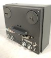
EDIT: The glory shot - well, actually it wasn't particularly
glorious, natural light hasn't been super great the last couple of days. I've made it as pretty as I could under the circumstances.
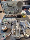
Below: Mods on the power supply board, top side.
 Update 2
: I found a spot with a bit of new white residue near C82 on the power supply board 2 weeks later, and there also is a slight urine-like smell which seems most prominent in the filter cap area. Methinks the poor old filter cap may have gone slightly incontinent, even if I wouldn't say the smell is very
fishy. Subjecting a 45-year-old 25 V type to a hair of 24 V did strike me as a bit risky, I will admit. I have a 1000µ/63 on hand that would be the exact size of the original (16x25 with 7.5 mm lead spacing), otherwise I could get 3300µ/50 and 4700µ/35 types in 18.5x35.5 locally that I reckon should fit as well... the slightly wonky C79 may need some persuasion, mind you.
Side note, there is no shortage of
bloopers among Kenwood tuners and their service docs. The KT-900 has to be one of the worst and screams "rush job" (nonexistent power connections, L2 bridged over, "wide" switching diodes running at like 3x the current they should - I have one of them bug collections on the way now, let's see how bad it really is). But even the KT-815 alignment instructions for the "noise amp" refer you to a phantom JFET Q3 (still listed on schematic but nowhere in sight) and phantom diode D8 (nowhere in sight either). And I guess only the designers themselves will know what the business with Q16 at the regulator is all about in the KT-1100. All of this makes the KT-80's misdrawn output connections looks downright negligible.