• WANTED: Happy members who like to discuss audio and other topics related to our interest. Desire to learn and share knowledge of science required. There are many reviews of audio hardware and expert members to help answer your questions. Click here to have your audio equipment measured for free!

Using two microphones to remove room modes from bass measurements

dominikz

Addicted to Fun and Learning
Forum Donor
Joined
Oct 10, 2020
Messages
806
Likes
2,638
I found this method very interesting so I decided to do a quick and dirty test of it with the tools I had on hand:
  • Neumann KH120A loudspeaker - I find this method especially interesting for loudspeaker with non-removable grills such as this one, where you can't really measure the LF driver in the ultra-nearfield (and therefore can't avoid some room influence with only one microphone)
  • Cross-Spectrum Labs calibrated Dayton EMM-6 microphone (used as the closer "Measurement microphone")
  • Rode NT2A in omni mode (used as the further "Mode microphone")
  • REW with multi-input capture license
Of course this test will be limited due to several reasons, main ones that I can identify:
  1. The two microphones used to measure are significantly different in construction.
    However their responses are reasonably close (+/-1dB) in the relevant range (40Hz-1kHz):
    1705010039343.png
  2. The sensitivity of the two microphones is slightly different - though I aligned the responses with preamp gain to within about 0,5dB
  3. The large body of the Rode NT2A will cause some undesired reflections in the higher midrange frequencies
  4. The distances between the two microphones (and microphone and driver) were only set approximately with a tape measure, similarly the angle of the microphone array axis to the driver was surely not exactly 90°
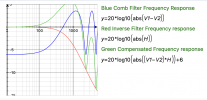
  5. Lastly I didn't apply the LP filter to remove the effect of the comb filter in the summed response
Setting the first microphone 5cm and the second 10cm from the driver, measuring and then using the REW alignment tool I was able to get the following response:
1705010825217.png


The black like is the summed response and we can see it is much smoother than either of the individual microphone responses - IMO showing that mode cancellation method works quite nicely. :) We also see the response doesn't contain the baffle step - which is as expected.

Note that responses arithmetically summed in REW don't contain harmonic distortion data of individual sweep measurements - which is something that a measurement done with the Mode Compensator would contain.

As a bonus, I also tried measuring with the first microphone ~15cm and the second ~30cm from the driver, this is what I got:
1705011423113.png


We see here the mode cancellation was less efficient this time, probably due to worse SNR at the increased distance from the driver.
Also, we see the shape of the response is different - IMO this is due to three reasons: 1) some baffle step may be present at this distance, 2) probably some of the port response is measured here as well (note that this is a front-ported speaker), and 3) comb filtering changes in frequency as we change the microphone distance (note that I'm not compensating for this in these measurements).

Hope this may be interesting to some! :)
 

AudioChiemgau

New Member
Joined
Feb 7, 2021
Messages
4
Likes
12
Well done!
Three remarks:
1) Also the phase frequency responses of the mics needs to match for best performance.
2) Without the comb filter frequency response measurements are limited to approximatively 100 Hz (compare blue shape of the first chart) for 5 cm distance between the mics.
3) Separating the two mics further results in the comb filter effect becoming already effective at lower frequencies, i.e. 30 Hz for 15 cm distance (compare the second chart). Your measurement fits well with the theory (compare the nulls). For larger mic distances one needs to adapt the inverse filter to get correct results again. As can be seen: Correction can be done up to approximately 500 Hz for 15 cm distance.
 

Attachments

  • Enzerrung FG.png
    Enzerrung FG.png
    830.1 KB · Views: 35
  • Bildschirmfoto 2024-01-12 um 07.48.48.png
    Bildschirmfoto 2024-01-12 um 07.48.48.png
    132.2 KB · Views: 37

dominikz

Addicted to Fun and Learning
Forum Donor
Joined
Oct 10, 2020
Messages
806
Likes
2,638
Well done!
Three remarks:
1) Also the phase frequency responses of the mics needs to match for best performance.
2) Without the comb filter frequency response measurements are limited to approximatively 100 Hz (compare blue shape of the first chart) for 5 cm distance between the mics.
3) Separating the two mics further results in the comb filter effect becoming already effective at lower frequencies, i.e. 30 Hz for 15 cm distance (compare the second chart). Your measurement fits well with the theory (compare the nulls). For larger mic distances one needs to adapt the inverse filter to get correct results again. As can be seen: Correction can be done up to approximately 500 Hz for 15 cm distance.
Thanks a lot for the very helpful comments and for sharing the details of your work - much appreciated!
 

SDX-LV

Active Member
Joined
Jan 11, 2020
Messages
135
Likes
143
Location
Sweden
I am now very confused about baffle step. So using Mode-Compensator there is no baffle step compensation needed because the measurement is not nearfield enough?
If I would measure a 6.5" driver without baffle or enclosure - what would baffle compensation be for Mode-Compensator or for nearfield measurement???
Looking forward to more tests by experienced DIY speaker measurement people.
 

Naturlyd

Member
Joined
Feb 24, 2021
Messages
21
Likes
58
I made a quick try as well. The idea was to test if its possible to isolate the frequency response of a subwoofer in a living room and to compare the response from two different placements in the room. Session 1 was with the sub placed 110 cm above floor level, on top of a large speaker in the middle of the room. In session two the sub was measured placed on the floor and closer to one wall. All in all not very symmetric.

As I plan on building new speakers with active cardioid to cancel SBIR I hope this method is useful. When adjusting the system it would be nice to have some data, not just make semi educated guesses along the way. Or maybe just stay confused but on a higher level.

DUT is the Dynavoice MW10, a cheap active "subwoofer" bought for testing out backwave cancelling. The crossover is bypassed and the bassreflex port is plugged with foam.

The microphones had pretty similar phase and frequency response. One is a Behringer ECM 8000 and the other is a Mic from Studio 6 that resembles the Behringer. It had a 0.6dB lower sensitivity which was compensated for.

Pictures of the setups:


image_67186945.JPG image_67191553.JPG

Here are the measurements, no smoothing. Sorry about poor readability of the comments :

MW10 110 cm up meas w Audiochiemgau method.jpg
MW10 on the floor meas w Audiochiemgau method.jpg


This is with the results from the Audiochiemgau method offset to the about the same level as the 5cm distance measurements. The 10cm measurements are also included.

MW10 on the floor SPL offset.jpg


MW10 110cm above floor with SPL offset.jpg


Edit: layout
 

Naturlyd

Member
Joined
Feb 24, 2021
Messages
21
Likes
58
Here the measurements from session 1 with the sub 110cm above floor level and session 2 placed on the floor. No smoothing. Pretty close?

Comparison MW10 on floor vs 110cm above.jpg
 

Naturlyd

Member
Joined
Feb 24, 2021
Messages
21
Likes
58
Most of you have read the background for this method. And why you need to compensate for the effect of the comb filter above 100Hz. I wonder if I did this correctly.

First I traced the filter shown in red, its from the documentation:


audiochiemgau filter 6db.png


Then I imported it into REW. You can see it being used i the posts earlier. Did I get it right?
 

ctrl

Major Contributor
Forum Donor
Joined
Jan 24, 2020
Messages
1,633
Likes
6,241
Location
.de, DE, DEU
I am now very confused about baffle step. So using Mode-Compensator there is no baffle step compensation needed because the measurement is not nearfield enough?

First, with the Mode-Compensator-Method (MCM), you cannot measure complete speakers, only individual drivers.

Even for support in speaker development, the MCM is actually no real improvement. With a 5cm and 10cm microphone measurement distance, the distance is already large enough for the baffle-step effect to begin affecting the measured near-field frequency response (FR) of the driver. This is something one would ideally want to avoid, as it introduces additional errors when later applying baffle-step correction to the measured near-field frequency response of the driver in the cabinet.

Additionally, in bass reflex or similar concepts, the BR, TL port, or PR at 5-10cm dust cap distance can already influence the measured FR, depending on their location (another potential source of error).

This means that with a "true near-field measurement" of the driver with <=1cm, better results are achieved when using the measurement for speaker development.

Here's a small example to illustrate this and an estimate of the sound pressure level (SPL) errors to expect. A free-field simulation without reflections (as this requires less effort than measuring it in reality) of a sealed speaker (CB concept, width 20cm, height 30cm, depth 23cm) with a 6.5'' woofer is "measured" at <1cm, 5cm, 10cm, and 200cm distances.
1707782356193.png
Then, the SPL of the FR measurements are level adjusted:
1707817724239.png


The red curve shows the FR of the driver in the CB enclosure at a distance of 2m. This corresponds to the measurement of the speaker in an anechoic chamber or by Klippel NFS.
The "true near-field measurement" with <1cm mic distance to the dust cap of the driver (-1.5cm from baffle) is shown as the blue curve. The two measurements at 5cm and 10cm dust cap distance (3cm and 8cm from baffle) for the Mode-Compensator-Method (MCM) are shown in purple and green, respectively. The result generated by the MCM lies between these two curves.

For speaker development, not much can be done yet, as the baffle-step correction has not been carried out to get as close as possible to the red curve, the free-field frequency response of the driver in the cabinet.

With a diffraction tool (like the diffraction tool from VCAD - which I used here and is based on a 2D simulation of the baffle, so expect some error, since the simulation is based on full 3D like in the real world), one can create a simple baffle-step correction and apply it to the near-field measurements. The goal is to get as close to the free-field 2m measurement of the woofer in the cabinet (red curve) as possible with the baffle step corrected near field measurements:
1707818156535.png

It becomes apparent here that the "true near-field measurement" (<1cm from dust cap) with baffle-step correction provides better results than MCM. With <1cm measurement distance to the dust cap, in real measurements practically no room reflections are included in the FR measurement. So no need for more complex MCM measurements.
But since the merging of the baffle-step corrected near-field measurement with the gated far-field measurement usually occurs around 300Hz, the additionally error of the MCM is not too bad for a CB concept woofer (with BR, TL or PR the error might be higher).

The MCM with baffle-step correction also cannot be used up to 1kHz, as the error compared to the free-field measurement is simply too large - with 2-3dB error in the 500-1000Hz range (see purple and green curves of the MCM).
 
Last edited:

ctrl

Major Contributor
Forum Donor
Joined
Jan 24, 2020
Messages
1,633
Likes
6,241
Location
.de, DE, DEU
If I would measure a 6.5" driver without baffle or enclosure - what would baffle compensation be for Mode-Compensator or for nearfield measurement???
Looking forward to more tests by experienced DIY speaker measurement people.
I haven't implemented any open baffle (OB) projects yet, but I've simulated several OB speakers.

If you measure a '6.5" driver without baffle or enclosure' in the near field, you're unlikely to succeed in generating a realistic baffle-step correction using standard software diffraction tools like VCAD to determine, for example, the free-field frequency response at a distance of 2m.
For such extreme cases, these tools are not suitable - at least based on my experience (which is solely based on simulations).

Either you simulate the free-field frequency response with a program like AKABAK, ABEC, Comsol,... for low frequencies and stich these simulated FR together with gated measurements or you try to obtain valid measurements down to frequencies where the driver exhibits the typical -6dB/oct behavior (for lower frequencies you can simply extend this behavior).
 

Naturlyd

Member
Joined
Feb 24, 2021
Messages
21
Likes
58
It would be nice if @AudioChiemgau took the time to comment on the simulations @ctrl did in post 28.

@ctrl: Thanks for the simulation. Is the baffle step correction represented by the blue line in the graph similar (same accuracy) as the correction one do in Vcad?
 

ctrl

Major Contributor
Forum Donor
Joined
Jan 24, 2020
Messages
1,633
Likes
6,241
Location
.de, DE, DEU
Is the baffle step correction represented by the blue line in the graph similar (same accuracy) as the correction one do in Vcad?
Thanks for pointing this out.
The diffraction tool used is from VCAD. I have amended the text in Post#28 accordingly.

So in the example we have a reasonably accurate 3D (BEM) simulation of the speaker. And then using a standard 2D based diffraction tool for the baffle step correction of the near-field "measurements" as it's standard in the real world when stitching near and far field measurements together.
 
Top Bottom