I'm assuming you're referring to the subwoofer output? If it's anything like the AO200, then it's 200 Hz.the da9 has a built-in low pass filter. do you know what frequencies it cuts?

-
WANTED: Happy members who like to discuss audio and other topics related to our interest. Desire to learn and share knowledge of science required. There are many reviews of audio hardware and expert members to help answer your questions. Click here to have your audio equipment measured for free!
- Forums
- Audio, Audio, Audio!
- Amplifiers, Phono preamp, and Analog Audio Review
- Stereo and Multichannel Amplifier Reviews
You are using an out of date browser. It may not display this or other websites correctly.
You should upgrade or use an alternative browser.
You should upgrade or use an alternative browser.
SMSL DA9 - Wait and see, or solid buy?
- Thread starter louis_lagrange
- Start date
mario_rouge
Active Member
- Joined
- May 29, 2021
- Messages
- 199
- Likes
- 95
sorry I still have a couple of questions. what is Soft Clipping for? what changes in the sound? do you keep it on or off? sometimes I hear a noise in the music like a scratched record. could it depend on the amplifier or the DAC? I have a SU9
jokan
Addicted to Fun and Learning
clipping is a phenomenon that occurs when a audio signal which is a sine wave has it's top and bottom clipped or you get momentary DC direct current in the audio. Music is alternating current.
It can happen for a variety of reasons. Speakers can clip, though it's usually when they are over-driven.
Clipping the input stage of an amplifier happens when you have too much voltage going into the amplifier.
Clipping the output stage connected to your speakers happens when the input signal is also being over driven.
https://en.wikipedia.org/wiki/Clipping_(audio)
It should never happen if your equipment is setup correctly. I had my DA-9 and my current A0200 set at max volume and i use my DAC (RME ADI-2 DAC fs) as the pre-amplifier. I had and have soft clipping turned off.
If you have the loudness turned on, bass cranked up then clipping becomes much easier to have happen. If you don't have the bass turned up and it's happening, then you have mismatched gains for the output from your DAC (it's too high), and the input of your amplifier. There are standard input voltages that audio equipment works with as well as input/output impedance (resistance) but these are generally standardised. Check your owners manual for proper operation and setup of your DAC.
It's difficult to understand what you mean by music sounding like a scratched record. There are a multitude of causes that can create that sort of noise.
Please let us know what speakers you have, how old they are. What DAC you're using, how old it is. We should be able to help you figure this out. For now, turn on soft clipping, it'll help protect your speakers.
mario_rouge
Active Member
- Joined
- May 29, 2021
- Messages
- 199
- Likes
- 95
I have some new Elac dbr62 and a dac su9 smsl. thank you so much you are very kind!
jokan
Addicted to Fun and Learning
Are you using XLR connections?
How are you connecting your speakers, stripped wires, or are you using banana plugs?
If you have stripped speaker wires, you must make sure that the wires are not accidentally touching anything else. One strand of wire touching anything can cause the outputs to short.
Speakers are not the problem, unless you somehow damaged them.
Your DAC is connected to a computer? Or are you using another device?
Try connecting your amplifier to your mobile, see if that same issue is there or not.
If the noise is gone when you use bluetooth mode for connection and not a wired connection, then you know it is not your amplifier or speakers.
It is also not likely to be your DAC. Connect your mobile to both your SU-9 and DA-9. switch the connections to see if one has noise or if both don't have noise. Process of elimination is your friend.
The next questions will be what type of computer, sound card etc are you using. What app are you using to play your audio files?
Why do I suspect that you have one of those RasPi devices?
Let me know what you find. Turn off all EQ settings no added bass or treble, go source direct before you do anything.
jokan
Addicted to Fun and Learning
I have some new Elac dbr62 and a dac su9 smsl. thank you so much you are very kind!
no problem, let's try and figure this out. It shouldn't be too difficult!
jokan
Addicted to Fun and Learning
I have some new Elac dbr62 and a dac su9 smsl. thank you so much you are very kind!
Did you manage to figure out what might be the cause? I'm curious for myself!
fluxcapacitor
Active Member
- Joined
- Dec 27, 2020
- Messages
- 115
- Likes
- 72
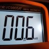
For the ones who measure high DC offset value on their DA9s;
it seems we've been measuring false value due to high frequency signals ... I read in a detailed review of SA300 recommending adding 10uH or 20uH inductors to speakers to eliminate unheard high frequencies due to unfiltered outputs of SA300. I had bought 10uH inductors for this reason and used with SA300.
I added same inductors to DA9 and fluctuating DC readings between 60mv-75mv dropped down to stable 4mv! Our voltmeters are fooled by high frequency signals and gives us false values.
Just add inductors and measure again.
Last edited:
- Joined
- Feb 25, 2021
- Messages
- 140
- Likes
- 141
Interesting find @fluxcapacitor ! Archimago brought that up in testing to remove high frequency noise that was disturbing measurements of the amp's frequency spectrum output as well. https://archimago.blogspot.com/2020/11/measurements-smsl-sa300-infineon-merus.html
What you insist is common sense for those who are knowledgeable about electronic circuits, and of course you should be careful when making measurements.For the ones who measure high DC offset value on their DA9s;
it seems we've been measuring false value due to high frequency signals ... I read in a detailed review of SA300 recommending adding 10uH or 20uH inductors to speakers to eliminate unheard high frequencies due to unfiltered outputs of SA300. I had bought 10uH inductors for this reason and used with SA300.
I added same inductors to DA9 and fluctuating DC readings between 60mv-75mv dropped down to stable 4mv! Our voltmeters are fooled by high frequency signals and gives us false values.
Just add inductors and measure again.
When measuring the DC offset voltage of a switching amplifier such as Class D, it is necessary to consider the high frequency noise contained in the output. The Infineon MA12070 chip allows high-frequency noise to leak with only a simple filter, and is expected to have a noise reduction effect when the speaker cable and speaker are included.
In SA300 and DA-9, high frequency noise is highest at the speaker output terminal of the amplifier and lowest at the speaker terminal.
Therefore, when measuring the DC offset voltage, measure it at the terminal on the speaker side. Never measure with the speaker terminal on the amplifier side. Also, if you do not use a good quality product for the digital multimeter you use, it will be affected by noise. Of course, music playback will stop when measuring.
If you pay attention to the above and measure it, you can get the correct value. If in doubt, connect a high frequency bypass capacitor in parallel to the measurement terminal.
jokan
Addicted to Fun and Learning
What you insist is common sense for those who are knowledgeable about electronic circuits, and of course you should be careful when making measurements.
When measuring the DC offset voltage of a switching amplifier such as Class D, it is necessary to consider the high frequency noise contained in the output. The Infineon MA12070 chip allows high-frequency noise to leak with only a simple filter, and is expected to have a noise reduction effect when the speaker cable and speaker are included.
In SA300 and DA-9, high frequency noise is highest at the speaker output terminal of the amplifier and lowest at the speaker terminal.
Therefore, when measuring the DC offset voltage, measure it at the terminal on the speaker side. Never measure with the speaker terminal on the amplifier side. Also, if you do not use a good quality product for the digital multimeter you use, it will be affected by noise. Of course, music playback will stop when measuring.
If you pay attention to the above and measure it, you can get the correct value. If in doubt, connect a high frequency bypass capacitor in parallel to the measurement terminal.
Inductors? Resistor perhaps at a stretch depending upon amplifier construction. Though I am happy to be proven incorrect.
Class-D amplifiers have internal inductors measured in mh to begin with.
Like I said, I am happy to be corrected. I invite it because i am still learning.
fluxcapacitor
Active Member
- Joined
- Dec 27, 2020
- Messages
- 115
- Likes
- 72
Yes im measuring at speaker terminal on the speakers and when a inductor is addet to + of speaker terminal DC readings drop to 4mv . Amplifier has no DC problem, we are just fooled by hf signals.What you insist is common sense for those who are knowledgeable about electronic circuits, and of course you should be careful when making measurements.
When measuring the DC offset voltage of a switching amplifier such as Class D, it is necessary to consider the high frequency noise contained in the output. The Infineon MA12070 chip allows high-frequency noise to leak with only a simple filter, and is expected to have a noise reduction effect when the speaker cable and speaker are included.
In SA300 and DA-9, high frequency noise is highest at the speaker output terminal of the amplifier and lowest at the speaker terminal.
Therefore, when measuring the DC offset voltage, measure it at the terminal on the speaker side. Never measure with the speaker terminal on the amplifier side. Also, if you do not use a good quality product for the digital multimeter you use, it will be affected by noise. Of course, music playback will stop when measuring.
If you pay attention to the above and measure it, you can get the correct value. If in doubt, connect a high frequency bypass capacitor in parallel to the measurement terminal.
Last edited:
fluxcapacitor
Active Member
- Joined
- Dec 27, 2020
- Messages
- 115
- Likes
- 72
Yes inductors and these infineon chips has no at all allows high frequencies to outputs.Inductors? Resistor perhaps at a stretch depending upon amplifier construction. Though I am happy to be proven incorrect.
Class-D amplifiers have internal inductors measured in mh to begin with.
Like I said, I am happy to be corrected. I invite it because i am still learning.
jokan
Addicted to Fun and Learning
I've already uploaded the exploded view of the A0200 which is next to identical to the DA-9
Please identify and use a paint program and show me the inductor(s) I know where they are and their is and the value, it's function in the circuitry.
Please identify the purpose of the inductor(s).
How many inductor(s) and what purpose do they serve in the PSU by Mornsun?
Thanks.
And here is the Chipset diagram furnished by Infineon/Merus for a single chip remember these amps have dual chipsets.
86 pages in total.
Again, I'm not looking for an argument. I'm looking for facts on how to "correctly" calculate DC-offset.
BTW, I've been doing the same measurement method as @Toku for years.
Attachments
Last edited:
It's great that you noticed and pointed out the effects of high frequency noise in measuring DC offset voltage. And trying various things is a very good experience. I hope your report will be of great help to everyone in the forum.Yes im measuring at speaker terminal on the speakers and when a inductor is addet to + of speaker terminal DC readings drop to 4mv . Amplifier has no DC problem, we are just fooled by hf signals.
I didn't explain much when I first pointed out the problem with the DA-9's DC offset voltage. When measuring, I only said that music playback should be stopped and the measurement should be performed on the speaker terminal side. I didn't say anything about high frequency noise because I wasn't good at English and it was a hassle to explain in detail.
The output filters of SA300 and DA-9 are very simple, just let the ferrite core (beads) pass through. Naturally, a lot of high frequency noise leaks to the speaker output terminal. Therefore, measuring the DC offset voltage there involves a lot of error. The leaked high-frequency noise is radiated as electromagnetic waves from the speaker cable and causes EMI damage around it. Therefore, Infineon specifies that the speaker cable should be 60 cm or less in the standard circuit. If it is longer than that, it is instructed to add an LC output filter. However, adding an LC output filter will worsen THD + N, so I would never want to add it as SMSL. I think the LC filter should be attached based on the actual usage of these amplifiers.
Since I was working with high frequency power amplification equipment from low frequencies to about 1000MHz, I have experienced a lot of the effects of high frequency noise.
Infineon manual materials are attached. If you are interested, please read it.
Attachments
jokan
Addicted to Fun and Learning
Thank you @Toku for the technical explanation.
There is far too much erroneous information out there with much speculation.
There is no arguing that all Class-D with switching amplification creates noise as a by product.
Some use more severe methods of "brick-wall" filtering the noise but the Infineon/Merus chip is designed to be "Hi-Res" and extends into the infrasonic frequencies far beyond the reaches of human hearing.
The PDF you included goes to great lengths to explain things. It still doesn't answer the questions I asked @fluxcapacitor to identify the inductor(s).
If one poses questions regarding the validity and methodology of the "correct" method of DC-offset testing then the correct methods must be applied. It cannot be "cherry picked" to give the best results. My A0200 is consistent at the speakers at 0.4-0.6mV. On occasion it spikes to over 1mV but that is well within reason and far from audible.
Electrical knowledge is fundamental along with the knowledge of how to follow a circuit without a circuit diagram to understand the basics. Of course it is very difficult to know exactly how SMSL wired the dual chipsets but it is easy to speculate with the 86 plus pages covering the application of a single chipset.
Thank you @Toku San for your clarification. I'm sure it helps many of us, including myself to have a greater understanding.
fluxcapacitor
Active Member
- Joined
- Dec 27, 2020
- Messages
- 115
- Likes
- 72
I see these obvious difference but i'm not sure if they are the reason of lesser noise ...Thank you @Toku for the technical explanation.
There is far too much erroneous information out there with much speculation.
There is no arguing that all Class-D with switching amplification creates noise as a by product.
Some use more severe methods of "brick-wall" filtering the noise but the Infineon/Merus chip is designed to be "Hi-Res" and extends into the infrasonic frequencies far beyond the reaches of human hearing.
The PDF you included goes to great lengths to explain things. It still doesn't answer the questions I asked @fluxcapacitor to identify the inductor(s).
If one poses questions regarding the validity and methodology of the "correct" method of DC-offset testing then the correct methods must be applied. It cannot be "cherry picked" to give the best results. My A0200 is consistent at the speakers at 0.4-0.6mV. On occasion it spikes to over 1mV but that is well within reason and far from audible.
Electrical knowledge is fundamental along with the knowledge of how to follow a circuit without a circuit diagram to understand the basics. Of course it is very difficult to know exactly how SMSL wired the dual chipsets but it is easy to speculate with the 86 plus pages covering the application of a single chipset.
Thank you @Toku San for your clarification. I'm sure it helps many of us, including myself to have a greater understanding.
but I can surely tell you that high DC readings on DA9s are due to HF noise,
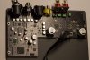
Below is the last DA9 i received with zero pop noise.
I'm using 10uH fixed inductor from Würth Elektronik, zero audible effect on the audio.
jokan
Addicted to Fun and Learning
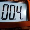
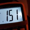
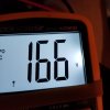
so explain these readings from my A0200?
Left and Right channels with no "dummy loading" after a about a week of use.
The readings before sufficient burn-in time are on the bottom, left and right.
Exactly the same method of measuring as @Toku. We share the same sort of electrical background though he actually studied for it and worked professionally as an EE for many, many years. I have about 30 years of Hi-Fi industry experience.
I'm not suggesting that your measurements or your methods are wrong. I am suggesting that there are many inconsistencies in technique. I hope you read the article that @Toku kindly posted that should further your understanding.
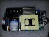
The I think they are Vishay Caps are on both models, I'll post a picture for you so you can see them, they are located on a different area no doubt for packaging reasons.
There is no argument from me. I'm just suggesting that between Toku-San and I we have many, many decades of professional experience. Unless we have both been wrong for multiple decades. I will tell you that I am 44, have been in the industry since I was 15 with a work permit in California, and later, much much later, about 10 years ago I moved to Japan. Still in the Hi-Fi industry.
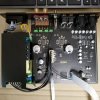
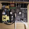
Picture of the aforementioned parts. Do you know what you highlighted btw?
And do you know what the parts that are on the A0200 but are not on the DA-9 are for?
There are a few major differences between the two amplifiers.
I can assure you that they are 99.5% the same sonically. I actually shipped mine back to Aoshida Hi-Fi Japan today to have a new model that actually reads Bluetooth and they will ship it back to me via FEDex.
Have you measured with the power and left over power within all the capacitors drained to see what parts you circled are? Do you know what they are, what they do, why they are there and why they are seemingly missing in the DA-9?
I will tell you that from my experience and during the short and I do mean short time I owned the DA-9, I found glaring flaws in execution. I left this board and moved over to the A0200 board because I sold my DA-9. I miss my A0200 right now but I have multiple tube amps, a few chip-amps, and another couple of Class-D amps.
The 0.04, 0.06 are taken after 10 minutes of idle time, and using sockets/banana's I've measured before and after the speaker cable, the measurements at the speaker are on average 0.02mV higher.
I'm actually sad that I sent my seemingly as close to perfect amplifier back to be replaced. I am fully expecting an amplifier that measures in the 0.3-0.4mV when I get a new one. Bare in mind that static measurements tell you if you have a MAJOR problem with your amplifier, anything over 60mV is not good, but brand new, it might be over 1mV at first, In a few hours or less it'll be nearly half unless there is a problem.
It's great that you are taking interest into how these amps operate but I would suggest highly that you learn about how amplifiers (esp Class-D) amplifiers are built. Why there are Zobel networks on speaker outputs on an amplifier for instance. And why speakers (most higher end speakers) have Zobel networks built in, so that's double Zobel-Networks! It's very interesting the theory becomes easier to understand as you learn more. In my case that meant I blew up, or smoked several amplifiers along the way from over-modding some amplifiers. I learned that if something sounds right from the factory that investigating and mucking around doesn't help, it usually does the other thing.
I hope you don't take this as a challenge, or as an insult. It isn't on both counts. I want people to understand circuits, how they work, why the parts are there. Why they were omitted in some cases. And why one op-amp might suit a specific purpose extremely well but that same op-amp might sound or work horribly in another circuit. These are interesting things to learn about. There's a reason why I have so ridiculously many op-amps left over and why I have favourites that I have multiple new units of that I have stored for a later day.
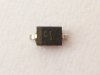
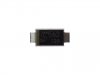
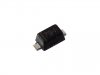
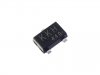
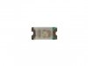
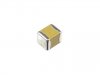
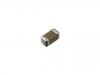
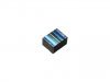
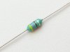
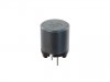
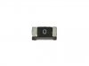
Towards the bottom I have added a slew of very similar shaped items, I know what each one does and can identify them, you can do the same if you can figure out what the numbers printed mean. I am only posting these pictures of SMD parts so you have an idea of what you circled are. And you have missed the single inductor that is on both the DA-9 and A0200 that is very obvious. I think you'll find it and it's nowhere near a 22mh inductor. Again I am not trying to be funny or whatever negative thoughts you might have. I am showing you how similar looking parts serve a very different purpose. And NO not all of these parts or similar ones are in either the DA-9 or the A0200. Some might be, but at different values and for a different purpose.
The only way I learned was from reading, and so on. I built my first amplifier from reading a book, memorising most of it, and built my first transistor amplifier from scratch at 10 years of age. It was much, much easier with transistors!
I do not know everything, I am constantly learning and being taught from my elders. Those who have been working with electronics for a VERY long time indeed.
One thing you learn after many many builds is that lets say two exactly the same value resistors fresh from the parts supplier measure within 0.01%. Then you apply voltage and it cycles power on/off a few times and that part that is a 0.5% part proves to be not only higher, but sometimes far lower even though you purchased them and cycled them exactly the same way and measured them in the same manner in within seconds of one another. This is a common occurrence and can be extremely frustrating when trying to make something that performs identically for 2 separate channels. I won't even get into gang error with volume pots. Some have insane error from left-right channel and are made and considered the "Velvet" standard. I actually don't use that brand because of their inconsistent performance. There are much better ways to have nearly error free 2 channel audio performance that is an analogue device. The question at that point is will it physically fit. Just like some of the discrete op-amps.
Since you show an obvious desire to learn, I encourage you to invest in books, measurement tools (try second hand oscilloscopes that have been refurbished PROPERLY. Once you have the tools, the better off you'll be and the more you will learn automatically. Your curious nature is something that needs to be nurtured. And don't be afraid to "Smoke" a few hopefully cheaper products. One great way of learning about Class D amplifiers is to modify one until you break it by exceeding it's limits. VERY easy to do. And always use better thermal paste than that white grease which is literally thrown in. Even your computer comes with that white grease unless you build your own. I use thermal paste rated at a minimum of 12.8. Usually I buy stuff that is 13.8 as it's good value. Standard white grease is somewhere in the low 2's. The higher the number, the more heat rejection/absorption potential it has.
Again, I'm not being critical. I'm glad you noticed the different layouts. There are several differences between the two. My A0200 just really opened up a few days ago, but I kept having the nagging feeling that if I don't take advantage of the fact that the latest A0200 without the typo would eventually bother me. So regardless of how well it measured, I decided to ask for the swap. Aoshida Hi-Fi Japan is extremely courteous and overly helpful. I asked them if I could wait a little while until I made up my mind. Their response was we'll exchange it whenever you'd like. They paid for shipping back to China and will pay for shipping from China to Japan for free. I can honestly say that I have not had such service from a Japanese company in years, probably decades.
Hope you figure out what those misc parts on the bottom are! They are all different. And there are a couple of red herrings in there!
Left and Right channels with no "dummy loading" after a about a week of use.
The readings before sufficient burn-in time are on the bottom, left and right.
Exactly the same method of measuring as @Toku. We share the same sort of electrical background though he actually studied for it and worked professionally as an EE for many, many years. I have about 30 years of Hi-Fi industry experience.
I'm not suggesting that your measurements or your methods are wrong. I am suggesting that there are many inconsistencies in technique. I hope you read the article that @Toku kindly posted that should further your understanding.
The I think they are Vishay Caps are on both models, I'll post a picture for you so you can see them, they are located on a different area no doubt for packaging reasons.
There is no argument from me. I'm just suggesting that between Toku-San and I we have many, many decades of professional experience. Unless we have both been wrong for multiple decades. I will tell you that I am 44, have been in the industry since I was 15 with a work permit in California, and later, much much later, about 10 years ago I moved to Japan. Still in the Hi-Fi industry.
Picture of the aforementioned parts. Do you know what you highlighted btw?
And do you know what the parts that are on the A0200 but are not on the DA-9 are for?
There are a few major differences between the two amplifiers.
I can assure you that they are 99.5% the same sonically. I actually shipped mine back to Aoshida Hi-Fi Japan today to have a new model that actually reads Bluetooth and they will ship it back to me via FEDex.
Have you measured with the power and left over power within all the capacitors drained to see what parts you circled are? Do you know what they are, what they do, why they are there and why they are seemingly missing in the DA-9?
I will tell you that from my experience and during the short and I do mean short time I owned the DA-9, I found glaring flaws in execution. I left this board and moved over to the A0200 board because I sold my DA-9. I miss my A0200 right now but I have multiple tube amps, a few chip-amps, and another couple of Class-D amps.
The 0.04, 0.06 are taken after 10 minutes of idle time, and using sockets/banana's I've measured before and after the speaker cable, the measurements at the speaker are on average 0.02mV higher.
I'm actually sad that I sent my seemingly as close to perfect amplifier back to be replaced. I am fully expecting an amplifier that measures in the 0.3-0.4mV when I get a new one. Bare in mind that static measurements tell you if you have a MAJOR problem with your amplifier, anything over 60mV is not good, but brand new, it might be over 1mV at first, In a few hours or less it'll be nearly half unless there is a problem.
It's great that you are taking interest into how these amps operate but I would suggest highly that you learn about how amplifiers (esp Class-D) amplifiers are built. Why there are Zobel networks on speaker outputs on an amplifier for instance. And why speakers (most higher end speakers) have Zobel networks built in, so that's double Zobel-Networks! It's very interesting the theory becomes easier to understand as you learn more. In my case that meant I blew up, or smoked several amplifiers along the way from over-modding some amplifiers. I learned that if something sounds right from the factory that investigating and mucking around doesn't help, it usually does the other thing.
I hope you don't take this as a challenge, or as an insult. It isn't on both counts. I want people to understand circuits, how they work, why the parts are there. Why they were omitted in some cases. And why one op-amp might suit a specific purpose extremely well but that same op-amp might sound or work horribly in another circuit. These are interesting things to learn about. There's a reason why I have so ridiculously many op-amps left over and why I have favourites that I have multiple new units of that I have stored for a later day.
Towards the bottom I have added a slew of very similar shaped items, I know what each one does and can identify them, you can do the same if you can figure out what the numbers printed mean. I am only posting these pictures of SMD parts so you have an idea of what you circled are. And you have missed the single inductor that is on both the DA-9 and A0200 that is very obvious. I think you'll find it and it's nowhere near a 22mh inductor. Again I am not trying to be funny or whatever negative thoughts you might have. I am showing you how similar looking parts serve a very different purpose. And NO not all of these parts or similar ones are in either the DA-9 or the A0200. Some might be, but at different values and for a different purpose.
The only way I learned was from reading, and so on. I built my first amplifier from reading a book, memorising most of it, and built my first transistor amplifier from scratch at 10 years of age. It was much, much easier with transistors!
I do not know everything, I am constantly learning and being taught from my elders. Those who have been working with electronics for a VERY long time indeed.
One thing you learn after many many builds is that lets say two exactly the same value resistors fresh from the parts supplier measure within 0.01%. Then you apply voltage and it cycles power on/off a few times and that part that is a 0.5% part proves to be not only higher, but sometimes far lower even though you purchased them and cycled them exactly the same way and measured them in the same manner in within seconds of one another. This is a common occurrence and can be extremely frustrating when trying to make something that performs identically for 2 separate channels. I won't even get into gang error with volume pots. Some have insane error from left-right channel and are made and considered the "Velvet" standard. I actually don't use that brand because of their inconsistent performance. There are much better ways to have nearly error free 2 channel audio performance that is an analogue device. The question at that point is will it physically fit. Just like some of the discrete op-amps.
Since you show an obvious desire to learn, I encourage you to invest in books, measurement tools (try second hand oscilloscopes that have been refurbished PROPERLY. Once you have the tools, the better off you'll be and the more you will learn automatically. Your curious nature is something that needs to be nurtured. And don't be afraid to "Smoke" a few hopefully cheaper products. One great way of learning about Class D amplifiers is to modify one until you break it by exceeding it's limits. VERY easy to do. And always use better thermal paste than that white grease which is literally thrown in. Even your computer comes with that white grease unless you build your own. I use thermal paste rated at a minimum of 12.8. Usually I buy stuff that is 13.8 as it's good value. Standard white grease is somewhere in the low 2's. The higher the number, the more heat rejection/absorption potential it has.
Again, I'm not being critical. I'm glad you noticed the different layouts. There are several differences between the two. My A0200 just really opened up a few days ago, but I kept having the nagging feeling that if I don't take advantage of the fact that the latest A0200 without the typo would eventually bother me. So regardless of how well it measured, I decided to ask for the swap. Aoshida Hi-Fi Japan is extremely courteous and overly helpful. I asked them if I could wait a little while until I made up my mind. Their response was we'll exchange it whenever you'd like. They paid for shipping back to China and will pay for shipping from China to Japan for free. I can honestly say that I have not had such service from a Japanese company in years, probably decades.
Hope you figure out what those misc parts on the bottom are! They are all different. And there are a couple of red herrings in there!
Attachments
-
 20210827_042829.jpg196.8 KB · Views: 97
 -
 20210827_042908_017.jpg224.3 KB · Views: 97
 -
 20210826_094003.jpg175.2 KB · Views: 109
 -
 20210826_094027.jpg165.5 KB · Views: 134
 -
 20210827_174627.jpg336.7 KB · Views: 131
 -
 I-02632.jpg130.1 KB · Views: 128
 -
 I-06282.jpg22.2 KB · Views: 106
 -
 I-06467.jpg22.1 KB · Views: 111
 -
 I-08768.jpg16.4 KB · Views: 113
 -
 I-15109.jpg6.2 KB · Views: 91
 -
 P-15444.jpg18.1 KB · Views: 101
 -
 P-13374.jpg9.6 KB · Views: 107
 -
 P-10477.jpg12.9 KB · Views: 106
 -
 P-03969.jpg167.3 KB · Views: 113
 -
 P-15690.jpg22.4 KB · Views: 90
 -
 R-11619.jpg10.3 KB · Views: 110
fluxcapacitor
Active Member
- Joined
- Dec 27, 2020
- Messages
- 115
- Likes
- 72
I was referring to differences at output stages that may explain the HF differences, was not talking about the entire pcb.so explain these readings from my A0200?
Left and Right channels with no "dummy loading" after a about a week of use.
The readings before sufficient burn-in time are on the bottom, left and right.
Exactly the same method of measuring as @Toku. We share the same sort of electrical background though he actually studied for it and worked professionally as an EE for many, many years. I have about 30 years of Hi-Fi industry experience.
I'm not suggesting that your measurements or your methods are wrong. I am suggesting that there are many inconsistencies in technique. I hope you read the article that @Toku kindly posted that should further your understanding.
The I think they are Vishay Caps are on both models, I'll post a picture for you so you can see them, they are located on a different area no doubt for packaging reasons.
There is no argument from me. I'm just suggesting that between Toku-San and I we have many, many decades of professional experience. Unless we have both been wrong for multiple decades. I will tell you that I am 44, have been in the industry since I was 15 with a work permit in California, and later, much much later, about 10 years ago I moved to Japan. Still in the Hi-Fi industry.
Picture of the aforementioned parts. Do you know what you highlighted btw?
And do you know what the parts that are on the A0200 but are not on the DA-9 are for?
There are a few major differences between the two amplifiers.
I can assure you that they are 99.5% the same sonically. I actually shipped mine back to Aoshida Hi-Fi Japan today to have a new model that actually reads Bluetooth and they will ship it back to me via FEDex.
Have you measured with the power and left over power within all the capacitors drained to see what parts you circled are? Do you know what they are, what they do, why they are there and why they are seemingly missing in the DA-9?
I will tell you that from my experience and during the short and I do mean short time I owned the DA-9, I found glaring flaws in execution. I left this board and moved over to the A0200 board because I sold my DA-9. I miss my A0200 right now but I have multiple tube amps, a few chip-amps, and another couple of Class-D amps.
The 0.04, 0.06 are taken after 10 minutes of idle time, and using sockets/banana's I've measured before and after the speaker cable, the measurements at the speaker are on average 0.02mV higher.
I'm actually sad that I sent my seemingly as close to perfect amplifier back to be replaced. I am fully expecting an amplifier that measures in the 0.3-0.4mV when I get a new one. Bare in mind that static measurements tell you if you have a MAJOR problem with your amplifier, anything over 60mV is not good, but brand new, it might be over 1mV at first, In a few hours or less it'll be nearly half unless there is a problem.
It's great that you are taking interest into how these amps operate but I would suggest highly that you learn about how amplifiers (esp Class-D) amplifiers are built. Why there are Zobel networks on speaker outputs on an amplifier for instance. And why speakers (most higher end speakers) have Zobel networks built in, so that's double Zobel-Networks! It's very interesting the theory becomes easier to understand as you learn more. In my case that meant I blew up, or smoked several amplifiers along the way from over-modding some amplifiers. I learned that if something sounds right from the factory that investigating and mucking around doesn't help, it usually does the other thing.
I hope you don't take this as a challenge, or as an insult. It isn't on both counts. I want people to understand circuits, how they work, why the parts are there. Why they were omitted in some cases. And why one op-amp might suit a specific purpose extremely well but that same op-amp might sound or work horribly in another circuit. These are interesting things to learn about. There's a reason why I have so ridiculously many op-amps left over and why I have favourites that I have multiple new units of that I have stored for a later day.
Towards the bottom I have added a slew of very similar shaped items, I know what each one does and can identify them, you can do the same if you can figure out what the numbers printed mean. I am only posting these pictures of SMD parts so you have an idea of what you circled are. And you have missed the single inductor that is on both the DA-9 and A0200 that is very obvious. I think you'll find it and it's nowhere near a 22mh inductor. Again I am not trying to be funny or whatever negative thoughts you might have. I am showing you how similar looking parts serve a very different purpose. And NO not all of these parts or similar ones are in either the DA-9 or the A0200. Some might be, but at different values and for a different purpose.
The only way I learned was from reading, and so on. I built my first amplifier from reading a book, memorising most of it, and built my first transistor amplifier from scratch at 10 years of age. It was much, much easier with transistors!
I do not know everything, I am constantly learning and being taught from my elders. Those who have been working with electronics for a VERY long time indeed.
One thing you learn after many many builds is that lets say two exactly the same value resistors fresh from the parts supplier measure within 0.01%. Then you apply voltage and it cycles power on/off a few times and that part that is a 0.5% part proves to be not only higher, but sometimes far lower even though you purchased them and cycled them exactly the same way and measured them in the same manner in within seconds of one another. This is a common occurrence and can be extremely frustrating when trying to make something that performs identically for 2 separate channels. I won't even get into gang error with volume pots. Some have insane error from left-right channel and are made and considered the "Velvet" standard. I actually don't use that brand because of their inconsistent performance. There are much better ways to have nearly error free 2 channel audio performance that is an analogue device. The question at that point is will it physically fit. Just like some of the discrete op-amps.
Since you show an obvious desire to learn, I encourage you to invest in books, measurement tools (try second hand oscilloscopes that have been refurbished PROPERLY. Once you have the tools, the better off you'll be and the more you will learn automatically. Your curious nature is something that needs to be nurtured. And don't be afraid to "Smoke" a few hopefully cheaper products. One great way of learning about Class D amplifiers is to modify one until you break it by exceeding it's limits. VERY easy to do. And always use better thermal paste than that white grease which is literally thrown in. Even your computer comes with that white grease unless you build your own. I use thermal paste rated at a minimum of 12.8. Usually I buy stuff that is 13.8 as it's good value. Standard white grease is somewhere in the low 2's. The higher the number, the more heat rejection/absorption potential it has.
Again, I'm not being critical. I'm glad you noticed the different layouts. There are several differences between the two. My A0200 just really opened up a few days ago, but I kept having the nagging feeling that if I don't take advantage of the fact that the latest A0200 without the typo would eventually bother me. So regardless of how well it measured, I decided to ask for the swap. Aoshida Hi-Fi Japan is extremely courteous and overly helpful. I asked them if I could wait a little while until I made up my mind. Their response was we'll exchange it whenever you'd like. They paid for shipping back to China and will pay for shipping from China to Japan for free. I can honestly say that I have not had such service from a Japanese company in years, probably decades.
Hope you figure out what those misc parts on the bottom are! They are all different. And there are a couple of red herrings in there!
What we see in DA9s are %100 hf frequencies that are not filtered. By adding a quality inductor all is settled. I'll be using inductor just to avoid sending unnecessary HF to my speakers as i used with my previous SA300 happily. From that point on , i see no reason to pay more for Aoshida version. Also SMSL logo issue was solved.
I also think DC measurement thing is way overrated here, my Marantz PM7000N which has mind blowing sound quality has 20mv stable for both channels, no pop, no hiss nothing. Keeping the mind busy for 1mv reading is quite unnecessary for me
")
Thanks for your recommendations though.
jokan
Addicted to Fun and Learning
You will not find a miniature high quality (audiophile grade) inductor that will work in the budget of either amplifier, or even both combined. Inductors are just coils. Depending on the amount of voltage going through them they will be of a different thickness of wire. Some have cores, others do not. I hear you loud and clear. The brick-wall filter they used at 22mh is there to stop 20khz and above tones for the sake of testing, the amplifier is capable of truly hi-res frequency response. I am certain that they used that testing sheet as an example only. If you don't like or enjoy the additional sibilance or highest of high frequencies then I totally understand. The amp will stop by design at around 50khz no matter what you do. And most DAC's have some sort of filter that stops the super high frequencies, or they are adjustable. You are one 100% correct DC-offset measurements became a thing on this thread because one person became obsessed by it. I actually was the last to measure my DA-9 that posted my numbers. I knew that it measured far lower than what the maximum was, and it was not as good as my A0200, but it was well below 0.9mV no matter what I did to it. Actually 0.5mV and 0.7ish was my memory for the DA-9.
20mV is perfectly healthy! 20-40mV is what i typically see for good performing amplifiers. There is something called run-away when DC-offset can literally run-away. Particularly dangerous to ribbon tweeters, and heil-motion tweeters like those found in some of the German made ELAC's and the newer Monitor Audio speakers. You can fry a tweeter without knowing it, well until it's too late!. The DA-9 is fractionally more "present" but the A0200 after a good while and plenty of cycling is 99.5% the same in sound. I would venture to say it sounds better because the noise floor is lower by simple fact of moving the stupid power supply. It's about as far away from one of the loudest noise makers inside the amplifier, the LED screen driver module. I hate those power drivers for LED screens. The Aoshida version has a few nice things about it that become apparent over time. Not immediately unless you are like me and hate screens that stay on. I have spoken at length with Aoshida Hi-Fi Japan's representative and he has told me a few of the key differences. SMSL's DA-9 is exclusively built by SMSL for Shenzen Audio. They therefore got first dibs. The A0200 is at least one generation more refined with some of the shortcomings resolved. It you have feel like your tweeters are too bright, a small, low amperage inductor/coil like the one seen in the link I believe you posted is not going to last you very long. I would highly advise against it. Plus that's a 20% tolerance part! If you want to tame the high-frequencies, use a brick-wall filter in your DAC (if you have one), or you can modify your speakers with an L-Pad an attenuator (the "correct" method to attenuate a loud speaker and to match it to the woofer, or mids/woofers). You can find a huge variety of audiophile grade inductors by companies such as Jantzen sold by several online vendors. They use typically air-coils and for what you are doing, you don't need super thick wire, but you want high quality, high tolerance parts.
https://www.parts-express.com/brand/Jantzen-Audio
You might consider learning about notch filters for speakers. You can design them yourself, the downside is that they use power hungry parts. A rule of thumb is 3db per part or more. You will need at least one part to quieten a speaker/tweeter combination. And remember that if it's going across both the woofer and tweeter, then it affects all frequencies. Should learn about Zobel Networks. They are used to take away impedance peaks, or to shift or create them.
I do see what you're driving at/for. I think you're going around it in not the best way. I worry that you have been misled with the reason why the inductors where used and though it maybe working/functioning right now, it is far from the correct way to achieve what you are after. I have inductors for speakers that are 0.01mh myself in my stash of parts for when I am building speakers and trying things out. I wind up finding other methods of curing the unwanted timbre or shimmer in the sound.
The EMI that is emitted from the power driver for the LED screen on the DA-9 can be heard by some people but only when they have their ear on the screen. The brightness level does not have any effect on the high pitched whine that can be heard on some units. That is one of the primary reasons why there is a different layout for the 2 units. The other is the built in DAC which to be brutally honest is as good as listening to a CD with a higher quality CD player. It is VERY good sounding. It also has dual sub-outs, and a few parts associated with the built in DAC. Some of the parts you have highlighted are for the DAC. Not for the sound of the A0200. The sound of the A0200 owes much to it's layout. Aoshida had the time to look at what SMSL for Shenzen Audio created and improved upon it. That is my observation along with several others. The DA-9 has a little bit more sparkle, I will agree with anybody who says so. The sparkle that is lost with the A0200 is only evident when you have both units set to the same volume, in the same room, with the same environment. I would be willing to put a blindfold on and I will more than likely get it correct over 75% of the time. Which do I prefer. It depends on my mood. Nothing that a treble adjustment can't fix on my RME, or on the A0200.
Please understand that what you are doing with a low current capable inductor is potentially dangerous. Certainly at higher volume levels you can burn your fingers if you touch the wires. They will get hot.
There are non-electrical ways to make your tweeters sound less forward or bright which is safe and inexpensive. little "Hacks" that you can perform with relative ease and can undo whenever you please. You can also turn the treble down, or depending on your equipment turn down specific frequencies.
I just don't want you to potentially damage your speakers which you can with a low power capacity, ultra low tolerance (20%) part that is used primarily for low level signals, we are talking way below 1volt in power. It's really without exaggeration potentially very dangerous for both yourself, your speakers, and can damage your amplifier if you use it permanently.
Please be careful. (The chances of the part failing before any danger is equally as high), but be careful nonetheless!
BTW, you are not comparing apples to apples, the Marantz is a much higher quality build and also a completely different design of amplifier! Nevermind the price difference.
To finish, I will always say that if you're happy that should be enough as long as you are not potentially damaging equipment.
Cheers!
Similar threads
- Replies
- 4
- Views
- 767
- Replies
- 6
- Views
- 895
- Replies
- 51
- Views
- 39K
- Replies
- 276
- Views
- 46K