• WANTED: Happy members who like to discuss audio and other topics related to our interest. Desire to learn and share knowledge of science required. There are many reviews of audio hardware and expert members to help answer your questions. Click here to have your audio equipment measured for free!

Single Revel F208 with low midrange output

My saga continue...

So remember how I couldn't remove the bass driver to access the crossover...? Well, no matter how hard I pushed the driver's magnet from behind, and despite my many attempts to slowly and gingerly loosen it using the screw holes—which I've done successfully on other stubbornly stuck drivers—the thing would not budge. I gave it a couple days hoping I would come up with a brilliant idea for how to do it. It came to me this afternoon in a moment of desperation: Install a wood screw into one of the holes such that it threads into the driver's baffle but not the cabinet and then pry it out with a small crowbar...

Well, the driver was so "wedged" in that the trim around the driver gave-out before the driver did, pulling portions of the gloss veneer around the trim clean off. If that's not enough, I can't even get the driver to fit back into the hole. (That single bass driver seems to be slightly too large for the hole; the other driver fits ever so slightly better.) So, now I have a single $2.5k speaker that has attenuated midrange and a chipped finish on the front face of the cabinet...ugh.

I guess now I'm just looking for sympathy folks :)

At this point, I'm seriously contemplating purchasing a single F208 to replace it or cut my losses and sell its pristine and perfectly performant twin. Does anyone have a line on a single F208? Alternatively, is anyone looking to pay top dollar for a single 208?

View attachment 181754
Wondering if this unit was messed with before? Was the 8” driver glued in or something compared to the other one that came out?

Makes one wonder
 
What a disaster. I really feel for you.

What on earth are Revel playing at with drivers stuck in so firmly they cannot be removed? That's utterly ridiculous at any price. Typical of Chinese construction not US made. Oh wait, aren't these Indonesian manufacture? Perhaps they are assembled so fast the adhesive/finish hasn't even dried properly. All I know was all furniture out of Indonesia when I was in the business had some of the worst formaldehyde emissions, like Chinese board. E0 doesn't exist for those guys. They were not even close to E2.

So, those driver screws are just wood screws into the MDF, not captive nuts/machine threads?

I really hope you can get out of this mess. If Revel/Harman had been more co-operative and less dissmissive in the first place with you, none of this would have happened.
 
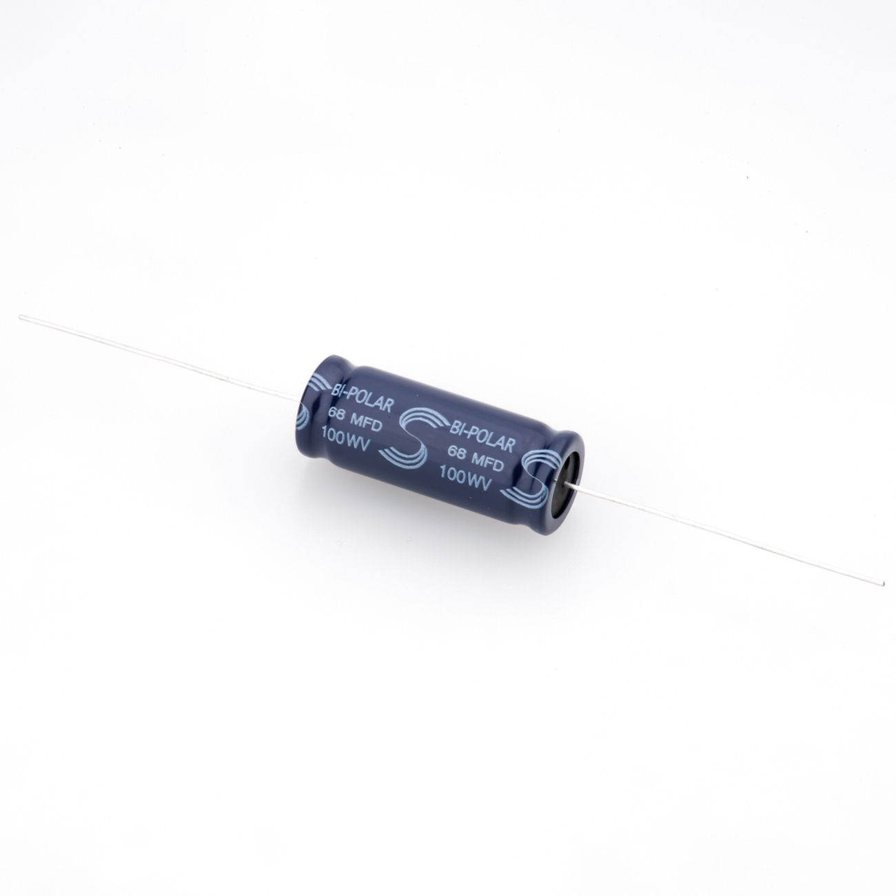
Can anyone elaborate on the capacitor specs I need and/or where I might source it from? Looks like 67uf 100v bipolar. Are there other values that would work here? Should I look for a particular grade or manufacturer? Do I necessarily need to replace the same cap on both crossovers, or just the one? Thanks again.
FC26E2F5-8638-4A65-BB1D-A19A39D58369.jpeg
 
That is such a bummer. It doesn’t even look like these were designed to ever be repaired. Which makes no sense to me. Surely there’s some QA at the factory. What do they do with the inevitable bad ones? Scrap the whole thing for want of a 50 cent part?
 
You can use 2x33uF NP in parallel and a single 1uF poly to give you 67uF and likely a better result. And you aren't hunting for a custom value.

That cap looks bad. ;(

Get the new caps in and test and if it's all good, I'd send Revel pictures of it, tell them the trouble you've had, reference their dismissive attitude and point them to this thread where you've had to get help to fix their product.

It will have already cost them a few sales so far.
 
Last edited:
You can use 2x33uF NP in parallel and a single 1uF poly to give you 67uF and likely a better result. And you aren't hunting for a custom value.
Yeh, I can’t find a 67uf anywhere online…

So I get the concept of summing the two 33uf + 1uf caps. But I’m having a hard time visualizing how I would wire them in parallel to the board, since the cap I’m replacing is bipolar. Can you help me out there?
 
I think you can reasonably safely say Bennic likely manufacture the crossover board/s and the attenuator/boundary boards as the values (c and r) are all custom Bennic. They do a lot of crossovers for many brands.


There would be no point getting Bennic to custom make capacitor/resistor/inductor values and then stuffing the crossovers at the Indonesian board processor making the cabinets. Bennic would do it and the crossovers would come in bulk, pre-made with looms, the drivers in bulk and the main cost (the cabinets) being done in a low labour cost facility in Indonesia.

You could always send the pic to Bennic- I bet they'd send you a bag full of caps.

[email protected]
 
But I’m having a hard time visualizing how I would wire them in parallel to the board, since the cap I’m replacing is bipolar. Can you help me out there?

Put one cap in the middle and and a cap either side. All are wired/soldered in parallel with the outer caps wrapping their lead wires around the inner cap leads which stay straight and go down through the holes in the PCB and are soldered. Zip tie the caps together or hot melt glue them.

Here's my quick Restorer-John high quality CAD drawing looking from the bottom:
1643184458903.jpeg


The two electros are of course BiPolar and the Poly is nonpolarized anyway. 100V rating on all of them.

If it all works well for testing and you want it back to original, get hold of a few 67uF caps from Bennic or Revel (hopefully free) and do it properly.
 
Dude my heart sank when I saw that damage. Sorry that it happened. Next time, try get crafty with mini screwdrivers or right angled tools and stick-mirrors, or, even pry the crossover board up - id rather smash the xo board up and remake it than damage a finish getting out a stuck driver. But hindsight is a bitch too.

The suggestion before of getting it back together and selling it to an AV enthusiast to use as a center behind a screen is an awesome idea.

Best of luck.
 
Put one cap in the middle and and a cap either side. All are wired/soldered in parallel with the outer caps wrapping their lead wires around the inner cap leads which stay straight and go down through the holes in the PCB and are soldered. Zip tie the caps together or hot melt glue them.

Here's my quick Restorer-John high quality CAD drawing looking from the bottom:
View attachment 181911

The two electros are of course BiPolar and the Poly is nonpolarized anyway. 100V rating on all of them.

If it all works well for testing and you want it back to original, get hold of a few 67uF caps from Bennic or Revel (hopefully free) and do it properly.
That’s incredibly helpful, thank you!
 
68uF bipolars are standard value crossover capacitors - I would swap them in both crossovers. No need to worry about the value -it's close enough.

I agree.

It's a little weird that Revel uses a 67uF cap when 68uF is a standard value and 67 is not.

In any case, 68 uF is close enough. It's less than 2% off, which is probably within the tolerance of the original.

So look for a 68 uF 100V electrolytic cap with a tight tolerance (<5% if you can find one).

I think you could even get away with just changing to 68 uF for this crossover and leaving the other speaker alone. I doubt you or anybody else could hear a difference. It would barely be measurable.
 
The easiest way if you need accuracy. Buy three 68 uF. Lend or buy a capacitance meter and choose the one closest to 67 uF.
 
I doubt you or anybody else could hear a difference. It would barely be measurable.
Yeah, but he would know they weren't the same and that's enough to drive anyone crazy... ;)
 

These have the axial terminations but it should work.

66-69 uf, the capacitance is not going to make a big difference.


So, is that flat black bezel a separate piece overlay on the baffle? Wondering if the bezel just covers the outer driver flange and was glued to the baffle. Reason I'm thinking that is the fact that you said you can't get the driver back in. Would explain why it lifted the finish on extraction.
 

These have the axial terminations but it should work.

66-69 uf, the capacitance is not going to make a big difference.


I picked up a few of these because they should ship quickly as the seller is pretty local to me. They look good?

 
So, is that flat black bezel a separate piece overlay on the baffle? Wondering if the bezel just covers the outer driver flange and was glued to the baffle. Reason I'm thinking that is the fact that you said you can't get the driver back in. Would explain why it lifted the finish on extraction.
I wondered that too, but it's securely glued on—at least it was until it inadvertently ripped off when I tried to remove the driver—and clearly not intended to be removed. That said, there is a little bit of a "lip" on the inside of that that seems to be what was keeping the driver from releasing from the cabinet. It makes for a nice, tight aesthetic presentation; but it obviously deters access to the internals.
 
I picked up a few of these because they should ship quickly as the seller is pretty local to me. They look good?

Those are polarized I think? You want non polar (NPE) / bipolar capacitors. A little more unusual but required for audio.

I would get the ones from parts express. I use them all the time.
 
Back
Top Bottom