Speedskater
Major Contributor
That's for sound traveling thru the air.The wavelength of 20kHz is less than an inch!
This discussion is about electrical signals traveling thru wires.

That's for sound traveling thru the air.The wavelength of 20kHz is less than an inch!
Don't forget that in a passive crossover there is already more inductance, capacitance and resistance in that crossover than in the any speaker wire you are talking about. The greatest contributor to all that crap between the amplifier and the driver is not the cable, its the passive crossover.
To add to your information this is handy too. One would need a fair amount of cable for a 2 Ohm wire.
If you mention the "speed of audio @ 20kHz", please be sure to state whether it's through air, a wire or whatnot.
20kHz wavelength in cable: around 15km
20kHz wavelength (acoustic) in air 17m
20kHz wavelength (acoustic) in water 80m
Wouldn't that air one be for 20 hz?
The high value woofer resistors are more likely in parallel with the speaker driver, and would not directly add to the resistance of the cable.
The harder the material, the faster sound (acoustic) goes through it.
By the bulk modulus which the counterpart of solids stiffness:I wonder how the "hardness" of a gas is determined...


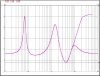
I checked back and the graph is wrong, thanks for pointing that out. The circuit shown is with 2.2uF 10R Zobel. The attached graph is (approximately) correct.OK. Here is figure 2 from the BS Audio article. You can see that both branches in the circuit have inductors, which block high frequencies. The left branch has a 330 uH one (lower than the right branch), and will have a lower impedance at high frequencies. At 100 kHz, ω=6.283e5 rad/s. Impedance (Z) from the 330 uH inductor is 1j*L*ω = 207j Ω. There is no way the impedance curve can level to 8 Ω at high frequencies. The impedance of this circuit rise to infinity as frequency goes to infinity.
So figure 2 alone is totally bogus. A total fail at basic electrical circuit. I am now afraid of these people with anything electrical. Can I stop now?
View attachment 94544
What test equipment model did you use to measure that impedance curve?I checked back and the graph is wrong, thanks for pointing that out. The circuit shown is with 2.2uF 10R Zobel. The attached graph is (approximately) correct.