• Welcome to ASR. There are many reviews of audio hardware and expert members to help answer your questions. Click here to have your audio equipment measured for free!

Pro-Ject Phono Box DS3 B Review

Rate this phono stage:

  • 1. Poor (headless panther)

    Votes: 8 5.6%
  • 2. Not terrible (postman panther)

    Votes: 34 23.6%
  • 3. Fine (happy panther)

    Votes: 88 61.1%
  • 4. Great (golfing panther)

    Votes: 14 9.7%

  • Total voters
    144
Brief update regarding 8kHz and 16kHz spikes: I measured the setup and am surprised that not only the balanced wiring between turntable and phono preamp, but also the balanced wiring between phono pre and AD converter picks up these spikes. Different cables make a noticeable difference. USB cable choice has an effect as well as plugging the USB cable into different USB ports in my PC.

I was not able to completely eliminate the 8kHz and 16kHz spikes and will turn off my PC when listening to vinyl.

Happy analog world ;-)
 
For those who are interested, and others with various levels of EMI OCD!

I found an EMI leakage point in the DS3 B mechanical design and addressed it. From the start I’ll state that I can’t hear a difference (because the levels are so low) but I can sure measure a difference.

I use the DS3 B with a MC cartridge so use the 60db gain setting. At one point I adjusted the load impedance while the system was at reasonably loud playing volumes, and I heard the distinct sound of injected mains hum, repeatedly; finger on knob – hum, finger off – no hum.

I took the DS3 B down to the mancave and put it on the test bench. This is what I found:

First, the REW performance on the test bench below. Conditions are: USB sound card is Xonar U7 MkII, located in cake tin (yes, a cake tin) to very effectively shield it from external EMI, DS3 B settings at XLR in, load at 150ohms and 60db gain and subsonic filter off (this filter makes quite a difference with 50hz hum components) to match my listening conditions. XLR inputs are open but this doesn't seem to make that much difference.

Here is the default spectrum on the test bench as the reference:

1720427250975.png


Here is the spectrum with my finger on the impedance load knob:

1720427286017.png


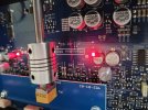
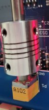
So, covers off and review of what the issue is. Well, the load knob has a metal connector shaft directly connected to the load potentiometer, with 60db of gain directly on the other side of the potentiometer, so the cause of the issue is quite simple.

Here is my solution:

1720427404719.png


I placed a length of copper foil with conductive adhesive backing to the shaft, some three rotations just to make sure, and connected the copper foil to a case earth point under the PCB mounting screw as shown.

When assembling the aluminium covers back on I was less that OCD happy with the internal shielding being aluminium only. So, I arranged a copper foil shield on a flexible substrate as shown in the photo below (I used a nickel impregnated fabric used for EM I shielding cut to size to cover the top and both left and right sides which don’t have any steel chassis coverage), but I guess one could use some A4 paper cut to size with the copper film. Photo below. The mounting screws for the aluminium panels pierce the copper cover and do connect to the chassis earth as needed.

1720427455506.png


Now after all of this, what is the difference: REW spectrum below.


1720427546793.png


In the first REW diagram the starting 50Hz hum level is at -88dbFS and very prominently standing out , in the modified version the 50hz hum is at -101dbFS and hiding, so a 13db improvement. There are also strange non mains-harmonic spikes here and there; no idea what they are, measurement artifacts I guess.

Now, I admit that the I have had to use large FFT lengths and multiple samples to return these spectrum's, as the EMI is well buried in the random noise generated by the 60db of gain in the DS3 B circuitry. So, as I stated at the start, one cannot hear the difference in use.

I have not bothered with a spectrum of me touching the impedance knob post modification, it is absolutely, completely, no different that the spectrum above; so, OCD mission accomplished.
 
Brief update regarding 8kHz and 16kHz spikes: I measured the setup and am surprised that not only the balanced wiring between turntable and phono preamp, but also the balanced wiring between phono pre and AD converter picks up these spikes. Different cables make a noticeable difference. USB cable choice has an effect as well as plugging the USB cable into different USB ports in my PC.

I was not able to completely eliminate the 8kHz and 16kHz spikes and will turn off my PC when listening to vinyl.

Happy analog world ;-)
Hi Mark, trying to limit the USB packet noise is a continuous issue. with the Xonar U7 MkII it is certainly breakthrough between the digital and analog sections of the USB interface as it is still there with the Xonar inputs shorted and the Xonar in a cake tin! The Xonar is only a >A$200 and I have had it a long time (my weak link). I understand that your RME interface is unlikely to experience this; but the USB packet noise is everywhere; just look at the spectrum in the earlier post with my finger on the DS3 B load knob!

I use a Topping USB isolator on the USB input to the Xonar to limit both mains interference and USB packet noise. Cable selection, as you mentioned, makes a difference. This issue is my biggest issue with my measurement system. In the final measurements above it does not show as the level is so low with respect to the overall noise level of the DS3 B.
 
Hi Stephen,
Thank you for sharing your mod with grounding the rotary knob.
This makes no difference with my unit - ProJect has implemented grounding of the poti housing in my newer hardware rev (notice the PCB numbering).
Worth checking before implementing the mod.
 

Attachments

  • Screenshot_20240710_233908_Gallery.jpg
    Screenshot_20240710_233908_Gallery.jpg
    117.9 KB · Views: 122
  • 20240710_112841.jpg
    20240710_112841.jpg
    271.3 KB · Views: 124
Hi Mark.
How interesting, I have rev01 of the potentiometer board and you have rev02. My DS3 B was purchased in March this year, and must have been 'New Old Stock' by then.

I was surprised that this earthing issue existed in the DS3 B, and I guess so did Pro-Ject......eventually.

I wonder what other improvements exist in new production runs?

Thanks for the insight.

Cheers
 
I purchased my device about a year ago...

Main PCB is rev03. Is this a newer version as well?

Wondering how valid test results are over the life cycle of such a product. Even worse with devices including substantial software, like a streamer...
 
Mark,

My main PCB is rev03 as well, what a relief! (452-01-03). Looks like I picked up an original shipped item that had been in long term storage at the dealer. I didn't order direct from Pro-Ject Australia as they were ~A$100 more in price. It doesn't matter to me, I have had great fun "improving" the measured performance.
 
Fun fact: I purchased a low cost Amazon Basic USB cable and now the 8kHz and 16kHz USB packet noise spikes on my analog input are completely gone. The USB cable I previously used obviouly was sh@%

I learned three things:
1) Always measure your setup.and ensure there are no issues.
2) Good cables do not need to be expensive ;-)
3) RME really should include a USB cable in their ADI-2 Pro box.
 
Last edited:
Does anyone with a DS3 B use the trigger input? I have a DS 3 power sources linear power supply with the 12v trigger out. The 2.5mm cable is showing 12v, but its not turning on the DS3 B phono
 
The DS3B has internal power supply circuits to generate positive and negative 16volt rails for the analog sections, and other power curcuits to generate the logic and relay control voltage supplies. The external 18vDC supply just provides the raw power input.
Are these psu circuits were created by using switching mode components or linear ones?
 
Last edited:
For those that are interested this is what the spectrum of the stock DS3B 18v switching power supply looks like on my simple measurement system.

The switching frequency of 24khz is prominent along with the harmonics up to the 96khz limit of the sample. The measurement system is basic but useable for this type of analysis, consisting of a Cro probe, 10uf polypropylene DC blocking cap and an ASUS Xonar MkII USB interface shielded from local EMI in a metal enclosure.

I have used a long REW FFT Length and 32 samples to discount random noise and reveal the persistent noise elements.

I thought this switching noise may impact the DS3B SNR and output noise artifacts. So, I assembled a simple two stage LC filter network to clean up the 18V DC supply before entry to the DS3B. This filter reduced the incoming 18V DC noise elements (using the same REW measurement configuration) by 40db at 100Hz and 20db at 10kHz with the switching noise nowhere to be seen.

The result: a miserly 1db improvement in the DS3B noise floor. So, it seems the DS3B has a well-engineered power supply arrangement within the box.

View attachment 359033
Can you please describe how I could build a similar gear to do my own measurements as you did? I assume the 10uF CAP needs to be in series to the output, what else do I need to safely connect a PSU to my audio interface? How do you calibrate it? Using a function generator?
 
Back
Top Bottom