• WANTED: Happy members who like to discuss audio and other topics related to our interest. Desire to learn and share knowledge of science required. There are many reviews of audio hardware and expert members to help answer your questions. Click here to have your audio equipment measured for free!

Power supply 'stiffness'

Ingenieur

Addicted to Fun and Learning
Joined
Apr 23, 2021
Messages
938
Likes
747
Location
PA
I did a crude test to see how much the 120 line drooped when playing music.

Set-up:
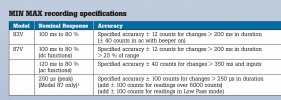
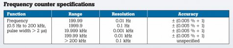
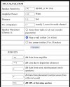
Fluke 87V, calibrated.
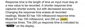
Took max/min/avg readings x 3, averaged for each measuring location:
Police 'Every Breath...' ~ 4 minutes each
80 dBA, I listen at 75, used ear muffs lol

Measuring locations:
Probes in receptacle
Probes in Furman PST8 (amp, computer, DAC) are supplied by it.

PU values, base is 123 VAC (just multiply the value x 123 to get the V, imo PU shows differences more clearly)

Vbase = 123, PU = 1.000
Reading......recept.......PST
Max- 1.000, 0.998
Min- 0.996, 0.995
Avg- 0.998, 0.996

My amp draws 150 VA at idle, 1.25 A
Music may have peaked at 20 W, another 0.7 A
~ 2 A peak
Max Vdrop at PST8 (0.998 - 0.995) x 123
0.37 V, 0.3%
Average 0.25 V, 0.2%
Tracked the receptacle, ie, followed it, no lag or damping.

No music, amp on, 0.1 V
No music, amp off, obviously 0.0

No impact
 
Last edited:

gnarly

Major Contributor
Joined
Jun 15, 2021
Messages
1,033
Likes
1,468
Lol...a good battery jump box with an inverter looks like it might power that load.

I needed a bit stiffer supply for the amps inside some big 4-way self-powered speakers i hung from the ceiling in a big playroom.
Numbers and measurements demanded some hefty sized AC lines.
MTS4a power.JPG
 

DVDdoug

Major Contributor
Joined
May 27, 2021
Messages
3,029
Likes
3,989
If the amplifier's power supply is well regulated the internal DC voltage will hold-up when the amplifier is putting-out full power (load regulation) and it will hold-up when the AC power varies within reason (line regulation).

Although line & load regulation have different names, usually the power supply's regulator takes care of both.

I just did an experiment with a 1800W hair drier, and the AC dropped by about 4V (at the same outlet).
 

audio2design

Major Contributor
Joined
Nov 29, 2020
Messages
1,769
Likes
1,831
Most linear power supplies for amplifiers are not overly regulated (if at all). Switch mode amplifiers of course are. Linear power supplies in audio are not power factor corrected beyond the odd choke regulation and even switch modes in audio rarely are at least it NA. Not been following the latest Euro regs for home stuff. I have measured 30+ amp peaks on big linear amps and subs.
 

sergeauckland

Major Contributor
Forum Donor
Joined
Mar 16, 2016
Messages
3,460
Likes
9,162
Location
Suffolk UK
According to my reading of UK wiring regs, the impedance of any mains circuit must be less than 0.25 ohms, in practice they're nearer 0.1 ohms. That means that drawing, say 10 amps, the voltage can't drop more than 2.5v, and in practice, around 1v. A HiFi Class AB amplifier will draw much less than 10 amps, typically less than 1 amps from our 230v mains on music, so voltage drop due to current drawn is totally inconsequential.

An amplifier draws power from the reservoir capacitors, not directly from the mains, so there's even that buffer. I have voltage and current metering on my HiFi rack, and the current draw for the whole system is stable at 500mA regardless of how loud I'm playing. I can get it up to 700mA only at levels that I can't stay in the same room. Voltage is pretty steady at 240v, with about +-2v variation during a typical day. Never seen less than 236v or more than 243v.

S
 
OP
Ingenieur

Ingenieur

Addicted to Fun and Learning
Joined
Apr 23, 2021
Messages
938
Likes
747
Location
PA
Unless you are tracking the instantaneous drop on a scope I am not sure what the value is of these measurements.
I am

The meter is fast.
250 uSec
4000 Hz
The power is < 400 Hz

I've used an ASCI tester. You plug it into a receptacle and it calculates the output Z of the circuit (indirectly). It gives the max SC current steady state, V/SC I = Z
As was mentioned depending on length most are 800-1200 range, 0.15-0.1 Ohm.
That includes everything: utility, xfmr, service, branch, etc.
It rises in about 1/4 cycle, 4-5 mSec.
Music can't draw power any faster.

The capacitors supply the excess until the line catches up. Since that is 240 Hz, and bass is the power user, it doesn't happen often if the PS is sized properly.
 
Last edited:

audio2design

Major Contributor
Joined
Nov 29, 2020
Messages
1,769
Likes
1,831
I am

The meter is fast.
250 uSec
4000 Hz
The power is < 400 Hz

You are misinterpreting the specs. It is 250usec peak measuring. That is much different from the instantaneous low at the top of the AC waveform (or high on the bottom). That's a 100msec response. Harmonics on a linear / non-PF corrected supply will be above 400Hz.
 
OP
Ingenieur

Ingenieur

Addicted to Fun and Learning
Joined
Apr 23, 2021
Messages
938
Likes
747
Location
PA
If the amplifier's power supply is well regulated the internal DC voltage will hold-up when the amplifier is putting-out full power (load regulation) and it will hold-up when the AC power varies within reason (line regulation).

Although line & load regulation have different names, usually the power supply's regulator takes care of both.

I just did an experiment with a 1800W hair drier, and the AC dropped by about 4V (at the same outlet).
1800 W, big load
15 A, ~ 0.26 Ohm, 0.27 Ohm, 3.3% drop
The target is <5% total
 
OP
Ingenieur

Ingenieur

Addicted to Fun and Learning
Joined
Apr 23, 2021
Messages
938
Likes
747
Location
PA
You are misinterpreting the specs. It is 250usec peak measuring. That is much different from the instantaneous low at the top of the AC waveform (or high on the bottom). That's a 100msec response.
No it isn't
It's the duration above the trigger.
The frequency counter works in the xx kHz range.
You are only measuring a 60 Hz signal
17 mS

Instantaneous only differs by the sqrt 2.
 

Attachments

  • 39000D4B-31DA-45C9-A508-C82841A687DC.jpeg
    39000D4B-31DA-45C9-A508-C82841A687DC.jpeg
    731.8 KB · Views: 42
  • 5CE2EA67-BEF6-4B48-97D8-77D9E8694747.jpeg
    5CE2EA67-BEF6-4B48-97D8-77D9E8694747.jpeg
    368.7 KB · Views: 54
Last edited:
OP
Ingenieur

Ingenieur

Addicted to Fun and Learning
Joined
Apr 23, 2021
Messages
938
Likes
747
Location
PA
There is a misconception that the music's frequency has something to to with power flow. Not really.

V and I will always be 60 Hz, power 120
V will ~ constant, less Vdrop due to current.
Your amp will not drag the grid down.
I will fluctuate based on the time constant of the PS .

Your amp will not induce transients. Those are supplied by the generator (or lightning).

Most amps are leading reactive loads due to PS C. It may increase V a bit when supplying reactive power to the lagging grid, but the V rise is only due to less Vdrop, due to less reactive power Q (less I) being supplied by the grid.

The worse case in a home is going to be an AC unit starting. Large inrush current.
 

audio2design

Major Contributor
Joined
Nov 29, 2020
Messages
1,769
Likes
1,831
No it isn't
It's the duration above the trigger.
The frequency counter works in the xx kHz range.
You are only measuring a 60 Hz signal
17 mS

Instantaneous only differs by the sqrt 2.

You are looking at instaneous of RMS of the whole waveform which is averaged over 100msec for the 87V. You are not measuring how much the peak drop is on the AC line.
 

audio2design

Major Contributor
Joined
Nov 29, 2020
Messages
1,769
Likes
1,831
There is a misconception that the music's frequency has something to to with power flow. Not really.

V and I will always be 60 Hz, power 120
V will ~ constant, less Vdrop due to current.
Your amp will not drag the grid down.
I will fluctuate based on the time constant of the PS .

Your amp will not induce transients. Those are supplied by the generator (or lightning).

Most amps are leading reactive loads due to PS C. It may increase V a bit when supplying reactive power to the lagging grid, but the V rise is only due to less Vdrop, due to less reactive power Q (less I) being supplied by the grid.

The worse case in a home is going to be an AC unit starting. Large inrush current.

I am an MSEE with extensive amplifier, switch mode and linear power supply design experience. I have no misconceptions wrt what is happening. The primary frequency of V, I is 60Hz. But I has significant high frequency content under heavy loads due to the nature of the linear and non-PF corrected switch mode supplies and that causes larger than expected instaneous V drop. Instaneous draw on the AC line can be 30+ amps on large subs and other big amps with commensurate large linear supplies though that's rare for subs now.
 
OP
Ingenieur

Ingenieur

Addicted to Fun and Learning
Joined
Apr 23, 2021
Messages
938
Likes
747
Location
PA
You are looking at instaneous of RMS of the whole waveform which is averaged over 100msec for the 87V. You are not measuring how much the peak drop is on the AC line.
It is measuring the min and max over a 4 minute period. It has a peak function.
It did not vary from the RMS min/max/avg
It did the same with pink noise and 20-400 Hz sweeps.
 

Attachments

  • 600CDF52-740A-4624-82BC-B64D3965BD86.jpeg
    600CDF52-740A-4624-82BC-B64D3965BD86.jpeg
    364.6 KB · Views: 50
OP
Ingenieur

Ingenieur

Addicted to Fun and Learning
Joined
Apr 23, 2021
Messages
938
Likes
747
Location
PA
I am an MSEE with extensive amplifier, switch mode and linear power supply design experience. I have no misconceptions wrt what is happening. The primary frequency of V, I is 60Hz. But I has significant high frequency content under heavy loads due to the nature of the linear and non-PF corrected switch mode supplies and that causes larger than expected instaneous V drop. Instaneous draw on the AC line can be 30+ amps on large subs and other big amps with commensurate large linear supplies though that's rare for subs now.
I have an MSEE, a grad certificate in power engineering and been a PE for 30 years. I design power systems for large facilities, like data centers, so I understand how loads impact source.

You will never induce more than a few % THD. Unless you are talking large VFD drives but there are ways to mitigate that.

Gotta flip an lp. McCoy Tyner.
 
Last edited:

audio2design

Major Contributor
Joined
Nov 29, 2020
Messages
1,769
Likes
1,831
I have an MSEE, a grad certificate in power engineering and been a PE for 30 years.

You will never induce more than a few % THD. Unless you are talking large VFD drives but there are ways to mitigate that.

Yes and I know you work on large scale power systems which is much different from what I do and what we are talking about here. Your equipment a Fluke 87V is incapable of measuring the instaneous V drop at the load on an AC signal and neither of us needs an MSEE for that. With a 60Hz high pass you could get some idea of the instaneous drop at the load. That said your amp sounds lightly loaded.
 
OP
Ingenieur

Ingenieur

Addicted to Fun and Learning
Joined
Apr 23, 2021
Messages
938
Likes
747
Location
PA
The PS xfmr L
Yes and I know you work on large scale power systems which is much different from what I do and what we are talking about here. Your equipment a Fluke 87V is incapable of measuring the instaneous V drop at the load on an AC signal and neither of us needs an MSEE for that. With a 60Hz high pass you could get some idea of the instaneous drop at the load. That said your amp sounds lightly loaded.

There is no 'instantaneous', a time must be specified. In the case 250 uSec
An 'instantaneous' ckt breaker is not.
The principles are applicable to both, power flow.

The meter will read the lowest V over time on a 60 Hz waveform. You will not see large drops, the load from an amp will not drag the V down 20% 'instantaneously'
At peak you may draw 5 amps (300 W), that may result in a 1 V drop. Likely less due to the PS C.

The L of the xfmr works both ways, it will attenuate higher harmonics. That is why isolation xfmrs or chokes/inductors are used on VFD (or other switching power devices).

I'm not sure what kind of drop you expect to see on a <3 A peak load.
My amp is quiescent 150 VA (supposedly class A up to 7 W).
So if it peaks at 2 A, 240 VA.
7 W + ~ (90 x 0.5) W ~ 50 W
The meters were reading ~15/ch
 
Last edited:

audio2design

Major Contributor
Joined
Nov 29, 2020
Messages
1,769
Likes
1,831
Did you miss the part where I said 30+ amps on very large subs and large amps with linear supplies? That's not theoretical and it is because of the capacitors. Some of those transformers are rated 1kw+ and that's a thermal rating. Heavy saturation does not kick in till 2-3x. For switch modes, the inductors on the front end are for high frequency filtering, i.e 150khz+. They don't do anything at near 60Hz, but the capacitance on the AC bulk side is much smaller for the same energy storage so peak draw is contained. Choke regulated supplies contain peak currents much better but you won't see that on a sub but fortunately not linear supplies either any more.
 
OP
Ingenieur

Ingenieur

Addicted to Fun and Learning
Joined
Apr 23, 2021
Messages
938
Likes
747
Location
PA
Did you miss the part where I said 30+ amps on very large subs and large amps with linear supplies? That's not theoretical and it is because of the capacitors. Some of those transformers are rated 1kw+ and that's a thermal rating. Heavy saturation does not kick in till 2-3x. For switch modes, the inductors on the front end are for high frequency filtering, i.e 150khz+. They don't do anything at near 60Hz, but the capacitance on the AC bulk side is much smaller for the same energy storage so peak draw is contained. Choke regulated supplies contain peak currents much better but you won't see that on a sub but fortunately not linear supplies either any more.

I'll take it down a notch.
Let's look at it practically

My amp 120 W/ch
xfmr 600 VA, 80,000 uF (I know, you know, this matters)
Speakers 86 dB/1 W @ 1 m
Set to 75 dBA at 12'
0.3 W/ch
Peak SPL ~ 98 or so, 50 W
100 W avg
200 W peak (sqrt2 V x sqrt2 I = 2 x P)
What kind of peak I would you expect to see? 400 VA?
How much from C?
3-4 A max?
 

Attachments

  • 454144D7-DFF4-4BC8-B29D-9E8D774C50D5.jpeg
    454144D7-DFF4-4BC8-B29D-9E8D774C50D5.jpeg
    392.4 KB · Views: 60
  • D30DCA72-8AB7-4B24-8213-CB42037E8DF5.jpeg
    D30DCA72-8AB7-4B24-8213-CB42037E8DF5.jpeg
    386.5 KB · Views: 50
Last edited:

audio2design

Major Contributor
Joined
Nov 29, 2020
Messages
1,769
Likes
1,831
I would probably simulate that because it's much faster than working out the math but you missed a critical spec to define the problem. What's the frequency of the peak? Most big peaks are low frequency, <120Hz and subs and big systems running room correction will put out huge wattage (1Kw is not crazy) . At low frequencies and big draw the caps will drop in voltage which causes high instaneous peaks for a short period of the waveform to refill the caps. That is why you can get big current peaks far higher than the average current (obviously) but higher than most, like you, expect. A good torture test for the supply is 120Hz tones 180 degrees out of phase with the mains ... Assuming 60Hz of course.
 
Top Bottom