@restorer-john great stuff

-
WANTED: Happy members who like to discuss audio and other topics related to our interest. Desire to learn and share knowledge of science required. There are many reviews of audio hardware and expert members to help answer your questions. Click here to have your audio equipment measured for free!
You are using an out of date browser. It may not display this or other websites correctly.
You should upgrade or use an alternative browser.
You should upgrade or use an alternative browser.
Kenwood KA-4020 Integrated amp. Would like to bypass amplification stage
- Thread starter Ast
- Start date
- Thread Starter
- #22
OP has stated he simply wants to use the unit as a preamplifier, my directions are to do just that in a non-invasive, reversible way.
Troubleshooting and repairing the power amplifier (if it actually has a fault) is a whole other story.
No need to ground the lifted R71/72 leads. They are there for him to inject a signal later should he wish to.
The fact that one channel is fine, suggests the power amp final stages are not actually damaged. The Class A front end (uPC1298), may be damaged, or the fault could be upstream. The uPC1237HA protector IC drives a single speaker relay. If there is a DC offset (from a fried output IC) the relay won't connect any speakers at all. So there is no harm leaving the power amp stage powered up, unused and input floating (it's tied by 100K to 0V anyway).
Attachments
- Thread Starter
- #23
Hi John, I really appreciate your support on this. Thanks for the suggestions but concerning the other suggestion I don't have the tools nor the dexterity to accomplish that task, dang those parts are way to small for me! I'll take my chances with the ribbon wire, I don't want to cut the wrong wires so could you help me out one last time by telling me on what side are the desired wires, so A or B? Thanks again.
Zek
Major Contributor
- Joined
- Feb 17, 2018
- Messages
- 1,616
- Likes
- 2,180
Don't cut any wire, just make some pins with solid hard wire to connect.I don't want to cut the wrong wires
To me it seems like it would be much easier to connect like John described. Are you in the USA or Canada? I can send you some shielded wire with solid 26AWG conductors (~0.016" dia). You should be able to slip the conductors underneath the jumpers and resistor leads and kind of wrap it around to make the soldering pretty easy. There are 2 conductors plus shield wire though, so you won't use one of the insulated wires.Hi John, I really appreciate your support on this. Thanks for the suggestions but concerning the other suggestion I don't have the tools nor the dexterity to accomplish that task, dang those parts are way to small for me! I'll take my chances with the ribbon wire, I don't want to cut the wrong wires so could you help me out one last time by telling me on what side are the desired wires, so A or B? Thanks again.
- Thread Starter
- #27
To me it seems like it would be much easier to connect like John described. Are you in the USA or Canada? I can send you some shielded wire with solid 26AWG conductors (~0.016" dia). You should be able to slip the conductors underneath the jumpers and resistor leads and kind of wrap it around to make the soldering pretty easy. There are 2 conductors plus shield wire though, so you won't use one of the insulated wires.
View attachment 26442
- Thread Starter
- #28
Hi, I'm in Québec Canada, I've got the wires and the soldering kit. But these pasts to cut and solder are sooo very small to me and I don't have the cutters. But I like Johns idea of using a pin, I'll try this and will let you know. Thanks again for your help.
- Thread Starter
- #29
I pull but cannot get it to budge, I'll figure out a way but need to know on what side the wires are situated, is it A or B ?What does the end of the ribbon cable look like when you disconnect it?
- Thread Starter
- #32
Hi John, I've completed the task and tested it on the AMP. 2 things: number one In order to get volume I must turn the know to at least 3/4 of it's travel and number 2 there's quite a lot of humming and buzzing, is it possible that my cable is picking this up from the transformer? If so how would I go about shielding it?OP has stated he simply wants to use the unit as a preamplifier, my directions are to do just that in a non-invasive, reversible way.
Troubleshooting and repairing the power amplifier (if it actually has a fault) is a whole other story.
No need to ground the lifted R71/72 leads. They are there for him to inject a signal later should he wish to.
The fact that one channel is fine, suggests the power amp final stages are not actually damaged. The Class A front end (uPC1298), may be damaged, or the fault could be upstream. The uPC1237HA protector IC drives a single speaker relay. If there is a DC offset (from a fried output IC) the relay won't connect any speakers at all. So there is no harm leaving the power amp stage powered up, unused and input floating (it's tied by 100K to 0V anyway).
Attachments
restorer-john
Grand Contributor
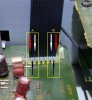
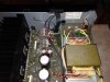
Zip tieing the shielded output cable to the power transformer secondaries is a no-no. You also must keep the three wires you've pulled apart as close together as possible, not leave them floating up in the air and route the cable carefully. Have you put RCAs on the rear panel or just run the cable out? If you have put chassis mount RCAs, use isolating washers and the PCB earth, not a chassis earth, or you may get hum from eddy currents in the chassis.
The front end is passive in direct mode, so the level will be relatively low. All you have between the line source and the output in direct mode is a 330 ohm resistor and the 100K pot. There is nothing wrong with using the volume pot up that far, as it is really just an attentuator in this case. Obviously, if you are using the RIAA stage or the tone controls, you switch in some active circuitry.
The front end is passive in direct mode, so the level will be relatively low. All you have between the line source and the output in direct mode is a 330 ohm resistor and the 100K pot. There is nothing wrong with using the volume pot up that far, as it is really just an attentuator in this case. Obviously, if you are using the RIAA stage or the tone controls, you switch in some active circuitry.
- Thread Starter
- #34
Zip tieing the shielded output cable to the power transformer secondaries is a no-no. You also must keep the three wires you've pulled apart as close together as possible, not leave them floating up in the air and route the cable carefully. Have you put RCAs on the rear panel or just run the cable out? If you have put chassis mount RCAs, use isolating washers and the PCB earth, not a chassis earth, or you may get hum from eddy currents in the chassis.
The front end is passive in direct mode, so the level will be relatively low. All you have between the line source and the output in direct mode is a 330 ohm resistor and the 100K pot. There is nothing wrong with using the volume pot up that far, as it is really just an attentuator in this case. Obviously, if you are using the RIAA stage or the tone controls, you switch in some active circuitry.
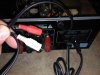
I cut an RCA cable and kept the male ends to plug directly into the AMP then passed the cable through a hole I made in the chassis and added a grommet. The wires are spread out only to show you and I'll do as you suggest when I reroute the cable. I'll reroute the cable but still would like to shield it (how can I do that) just in case.
I understand the volume level but I would have liked to be able to have better control on it, now it's low and full blast and hardly anything in between lol !
Again, your support is greatly appreciated, thanks again.
Attachments
- Thread Starter
- #35
Zip tieing the shielded output cable to the power transformer secondaries is a no-no. You also must keep the three wires you've pulled apart as close together as possible, not leave them floating up in the air and route the cable carefully. Have you put RCAs on the rear panel or just run the cable out? If you have put chassis mount RCAs, use isolating washers and the PCB earth, not a chassis earth, or you may get hum from eddy currents in the chassis.
The front end is passive in direct mode, so the level will be relatively low. All you have between the line source and the output in direct mode is a 330 ohm resistor and the 100K pot. There is nothing wrong with using the volume pot up that far, as it is really just an attentuator in this case. Obviously, if you are using the RIAA stage or the tone controls, you switch in some active circuitry.
Hi John, I've passed the cable on the other side away from the power supply as far as I could. I wrapped the cable in aluminum duct tape and put electrical on top of that to make sure that it did not touch any part of the chassis or anything else. Did not change a thing unfortunately. It seems to be internal.
- Thread Starter
- #36
What does the end of the ribbon cable look like when you disconnect it?
Hi, I'm not getting answers from John, do you have any suggestions? I've passed the cable on the other side away from the power supply as far as I could. I wrapped the cable in aluminum duct tape and put electrical on top of that to make sure that it did not touch any part of the chassis or anything else. Did not change a thing unfortunately. It seems to be internal.
Maybe you did not ground the shield? I don't know if you want to use shielded cable anyway since the ribbon is not shielded. You might just want small wires well routed to the RCAs on the panel. Anyway I'm afraid I'm not going to be able to help much, although I'd still be happy to send the shielded wire (I am in NH so it should get to you quickly).
Be patient with John - he'll probably get back to you.
Be patient with John - he'll probably get back to you.
- Thread Starter
- #38
Maybe you did not ground the shield? I don't know if you want to use shielded cable anyway since the ribbon is not shielded. You might just want small wires well routed to the RCAs on the panel. Anyway I'm afraid I'm not going to be able to help much, although I'd still be happy to send the shielded wire (I am in NH so it should get to you quickly).
Be patient with John - he'll probably get back to you.
Thanks my friend but I think that it will not be necessary, your support is very much appreciated. Although I don't understand why it's not working and if this does not work out, then I'll just go ahead and buy a pre amp. This was just a project.
restorer-john
Grand Contributor
Hi, I'm not getting answers from John, do you have any suggestions?
The hum you are getting is most likely due to the fact you removed the ribbon cable (L/R/Gnd) instead of following the suggestions I gave you on soldering directly to the components and earth point (J153) on the power amp PCB I identified for you in post #18.
Use J153 (jumper) as your ground point (easy to solder to a top board link) for any shielded cable you are running for a 'pre-amp out'.
What you have effectively done is this (you have cut the 'earth' reference for pin 2):
Cheers.
Similar threads
- Replies
- 0
- Views
- 404
- Replies
- 3
- Views
- 1K
- Replies
- 3
- Views
- 742
- Replies
- 7
- Views
- 603
- Replies
- 8
- Views
- 535