Hi my KA-4020 is not working properly 1 of the channels is not performing well. I'm not a tech but I would like to be able to bypass the amplification stage and use it as a preamplifier instead. What would be the easiest way to go about it? Thanks.

-
WANTED: Happy members who like to discuss audio and other topics related to our interest. Desire to learn and share knowledge of science required. There are many reviews of audio hardware and expert members to help answer your questions. Click here to have your audio equipment measured for free!
You are using an out of date browser. It may not display this or other websites correctly.
You should upgrade or use an alternative browser.
You should upgrade or use an alternative browser.
Kenwood KA-4020 Integrated amp. Would like to bypass amplification stage
- Thread starter Ast
- Start date
Use one of the tape outputs but you'll probably have to add a volume control.
- Thread Starter
- #3
Thanks Don, I knew that and the reason I want to use it as a preamp is to be able to use the volume control and the rest. I'm thinking that if I could redirect the output volume to a pair of outboard RCA jacks that would be great. I have the service manuel but have absolutly no idea how to read itUse one of the tape outputs but you'll probably have to add a volume control.

Do you know the problem is in the output amplifier and not before?
My next advice would be to use the headphone output with an adapter cable to your power amp. Check to see that the problem does not exist in the headphone outputs, though, as some (at one time many) receivers just route the main outputs to the headphone jack.
If that does not work and/or you want an "internal" solution but can't read a schematic, my advice would be to find a techie friend who can, and have him/her solder a couple of cables from before the power amp (after volume control and processing) to one of the tape outs.
- Thread Starter
- #5
Thanks Don that's a good idea and I'll try it. Question for you, do you think that it would also be possible to use the output directly from the 'Balance' selector. Would the volume control pass through the 'Balance' knob before going to the amplification stage?
Depends upon the receiver and I do not have a service manual. Maybe... Some place it after the volume control, but many place the volume control at the end of the chain so any added noise and distortion from various circuits is reduced by the volume control (with the desired signal) before the signal is passed on to the power amplifiers.
Can you solder? Again, if you cannot read a schematic (and I am NOT implying anything by that; I can't read a medical chart but my wife can), will you know exactly what wires to attach and where?
Can you solder? Again, if you cannot read a schematic (and I am NOT implying anything by that; I can't read a medical chart but my wife can), will you know exactly what wires to attach and where?
- Thread Starter
- #7
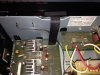
The black stripe is a ribbon cable containing multiple wires. If that is the amp board to the left, you may be able to pull the ribbon connector, remove power from the amp (to prevent it from oscillating or whatever), and tap into the amplifier's input from the cable to a couple of RCA jacks.
@restorer-john may be able to offer more help; he is a font of knowledge for things like this.
@restorer-john may be able to offer more help; he is a font of knowledge for things like this.
- Thread Starter
- #9
That's exactly what I want to do! Thanks I'll try to connect John, have a good day and thanks again!The black stripe is a ribbon cable containing multiple wires. If that is the amp board to the left, you may be able to pull the ribbon connector, remove power from the amp (to prevent it from oscillating or whatever), and tap into the amplifier's input from the cable to a couple of RCA jacks.
@restorer-john may be able to offer more help; he is a font of knowledge for things like this.
Do you know the problem is in the output amplifier and not before?
My next advice would be to use the headphone output with an adapter cable to your power amp. Check to see that the problem does not exist in the headphone outputs, though, as some (at one time many) receivers just route the main outputs to the headphone jack.
If that does not work and/or you want an "internal" solution but can't read a schematic, my advice would be to find a techie friend who can, and have him/her solder a couple of cables from before the power amp (after volume control and processing) to one of the tape outs.
It does like the headphone out is just the speaker outputs run through 150 ohm resistors, so the headphone output probably is not a solution. If you are opening this anyway to tap the preamp output, I would check the solder joints on the connector headers. Maybe that's all that is causing the problem. Personally I would not bother trying to use this if you can't fix the problem with the bad channel.
The headers at both ends of the connection between (X11-2902-70) and (X09 B/5) boards. I think this is also where you would want to tap in if you want to convert this to a preamp. But if @restorer-john replies forget anything I've offered and listen to him.
See if you can find one of these signal tracers: https://www.element14.com/community/thread/48371/l/signal-tracer-old-school?displayFullThread=true
You then connect one lead to the ground and then touch each pin on the ribbon cable until you hear music.
You then connect one lead to the ground and then touch each pin on the ribbon cable until you hear music.
restorer-john
Grand Contributor
@restorer-john may be able to offer more help
Sorry, late to the party.
Here's the relevant part of the schematic and where you can tap off the preamplifier front end from the power amp. Pins 1 and 3 of connector 2 (the ribbon cable) are R and L respectively. (obviously referenced to ground Pin2)).
You da' man! Thanks John!
- Thread Starter
- #16
Thanks,
I'll do my best to find the in the amp, thanks!Sorry, late to the party.
Here's the relevant part of the schematic and where you can tap off the preamplifier front end from the power amp. Pins 1 and 3 of connector 2 (the ribbon cable) are R and L respectively. (obviously referenced to ground Pin2)).
View attachment 26429
- Thread Starter
- #17
Reference ground pin 2, is that the 2 in the circle indicated LINE-E ? If you look at the image is 1 to the left or to the right of the picture, the picture that I took earlier?Sorry, late to the party.
Here's the relevant part of the schematic and where you can tap off the preamplifier front end from the power amp. Pins 1 and 3 of connector 2 (the ribbon cable) are R and L respectively. (obviously referenced to ground Pin2)).
View attachment 26429
Last edited:
restorer-john
Grand Contributor
Reference ground pin 2, is that the 2 in the circle indicated LINE-E ? If you look at the image is 1 to the left or to the right of the picture, the picture that I took earlier?
Yes. the ground can be anything attached to pin2, the closer the better to the ribbon cable. J153 should do it.
You can lift one leg (the right side on this pic) of R71 and R72 and solder to those two lands. Does the same thing and you don't have to mess about with the ribbon cable. Use J153 (jumper) as your ground point (easy to solder to a top board link) for any shielded cable you are running for a 'pre-amp out'.
Note: the Pin numbers are marked on the board layout above 1 and 12.
Here's the parts highlighted on your picture, you can do it all from above (snip one leg of R71/72) and that will save a whole lot of grief getting the power amp board off the base plate. Likely there is no access underneath in any case. There appears to be plenty of lead length on the resistors, so cut in the middle of the lead, that way you can solder to the board pigtail from above for your preamp-outs, tap into the power stage, or return it all to stock very easily.
*The reason I am suggesting the method above, rather than simply unplugging the ribbon cable and swinging out pins 1-3 is due to the fact that this black plastic covered ribbon is not tolerant to repeated soldering, is more likely to short out, and once soldered, you'll never get it back in the edge connector again if you decide to return it to stock.
Cheers.
Last edited:
Here's the parts highlighted on your picture, you can do it all from above (snip one leg of R71/72) and that will save a whole lot of grief getting the power amp board off the base plate.
Would you say that, assuming of the power amp channels has a problem, that it is important to do it as you describe and break these R71 and R72 connections to make sure the power amp problem does not affect the preamp? Should he ground the lifted R71/72 resistor leads?
restorer-john
Grand Contributor
OP has stated he simply wants to use the unit as a preamplifier, my directions are to do just that in a non-invasive, reversible way.
Troubleshooting and repairing the power amplifier (if it actually has a fault) is a whole other story.
No need to ground the lifted R71/72 leads. They are there for him to inject a signal later should he wish to.
The fact that one channel is fine, suggests the power amp final stages are not actually damaged. The Class A front end (uPC1298), may be damaged, or the fault could be upstream. The uPC1237HA protector IC drives a single speaker relay. If there is a DC offset (from a fried output IC) the relay won't connect any speakers at all. So there is no harm leaving the power amp stage powered up, unused and input floating (it's tied by 100K to 0V anyway).
...I would like to be able to bypass the amplification stage and use it as a preamplifier instead...
Troubleshooting and repairing the power amplifier (if it actually has a fault) is a whole other story.
No need to ground the lifted R71/72 leads. They are there for him to inject a signal later should he wish to.
The fact that one channel is fine, suggests the power amp final stages are not actually damaged. The Class A front end (uPC1298), may be damaged, or the fault could be upstream. The uPC1237HA protector IC drives a single speaker relay. If there is a DC offset (from a fried output IC) the relay won't connect any speakers at all. So there is no harm leaving the power amp stage powered up, unused and input floating (it's tied by 100K to 0V anyway).
Similar threads
- Replies
- 0
- Views
- 389
- Replies
- 3
- Views
- 1K
- Replies
- 3
- Views
- 730
- Replies
- 7
- Views
- 563
- Replies
- 8
- Views
- 492