Bartholomeus
Member
First of all I want to thank the ASR community for all the great readings I had the past few months, it helped me a lot making discissions for my new audio gear without all the fuss.
My audio setup is as follows:
Source: PC (USB)
DAC: Topping D50 III
Power amp: Audiophonics AP300-S250NC (Hypex NC-252MP)
Speakers: Bowers & Wilkins 707 S2
What bothers me is the fact I only have digital volume control, especially after reading some cases where the DAC went on to 100% volume. I’ve had a similar issue in the past with an older integrated amp so I want to put a potentiometer (ALPS RK27 10KOhm Quad channel) in between the DAC and Poweramp.
Of which I thought to be a simple implementation, turned out to be a headache for the past week.
I think I’ve worked it out how to implement the potentiometer but I’m still stuck at some points of which I hope you guys can help me.
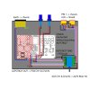
Current wiring: (ALPS RK27 10KOhm Quad channel)
XLR Pin #1 to Chassis
XLR “side” pin to shield
XLR Pin #2 & #3 to Potentiometer IN
Potentiometer OUT to PCB pin #1, #2 and #15, #16.
Potentiometer GND to PCB bolt
Shields connected without touching the Potentiometer.
I did a short test run with some loose wires and It all seemed to work correctly.
My questions:
1. Is the GND from the potentiometer to the PCB correct?
2. What do I do with the floating end of the shield near the PCB? Do I just cut it?
(Of what I’ve read the original way Audiophonics connected it to the PCB Pin #3 and #14 would be
wrong)
3. Are there any other things I have to take in consideration?
This is my first time doing something like this with an amplifier so I hope you guys can point me in the right direction.
I’ve added a drawing of the current idea.
(Edit 1: Potentiometer is a ALPS RK27 10KOhm. The amplifier does have a on/off switch but i would prefer a hard limit on the volume)
Attachments
Last edited:


