• WANTED: Happy members who like to discuss audio and other topics related to our interest. Desire to learn and share knowledge of science required. There are many reviews of audio hardware and expert members to help answer your questions. Click here to have your audio equipment measured for free!

Handling a complex load by power amplifiers

Sokel

Master Contributor
Joined
Sep 8, 2021
Messages
6,111
Likes
6,178
Hi all,

alright, is there any hints on amplifier datasheet to indicate it would work fine also on these complex loads?
Would it be correct to assume that if an amplifier adverts to be able to work on say 2ohm loads then it would indicate good ability to supply current for reactive loads on nominal 4 or 8ohm speakers?

Googling with power factor correction many high watt PA amplifiers seem to advert PFC on their power supplies. An advert I watched yesterday from Youtube seemed to suggest this PFC is what enables it for 2ohm loads. So, in case of these class D chip amps I'd guess its about cooling of the device and PSU that makes or breaks the performance.

Also, there is simple way to "fix" the complex load by adding parallel resistor to the amp output / speaker input. This resistor draws extra current and power, but if it sufficiently reduces heat generated inside the amplifier the net effect could be close to zero extra heat waste? Seems simple fix, so probably not true?:)
I don't think PFC has to do with the amp's ability for 2 ohm.Mine for example (icePower 1200as2) has PFC but can only go down to 2.7 ohm according to it's specs.
I think PFC has more to do with it's ability for universal mains power.
 
D

Deleted member 48726

Guest
Hi all,

alright, is there any hints on amplifier datasheet to indicate it would work fine also on these complex loads?
Would it be correct to assume that if an amplifier adverts to be able to work on say 2ohm loads then it would indicate good ability to supply current for reactive loads on nominal 4 or 8ohm speakers?

Googling with power factor correction many high watt PA amplifiers seem to advert PFC on their power supplies. An advert I watched yesterday from Youtube seemed to suggest this PFC is what enables it for 2ohm loads. So, in case of these class D chip amps I'd guess its about cooling of the device and PSU that makes or breaks the performance.

Also, there is simple way to "fix" the complex load by adding parallel resistor to the amp output / speaker input. This resistor draws extra current and power, but if it sufficiently reduces heat generated inside the amplifier the net effect could be close to zero extra heat waste? Seems simple fix, so probably not true?:)
PFC in some amps are in place to obide to national legislations IR to grid load. Europe typically.
 

DonH56

Master Contributor
Technical Expert
Forum Donor
Joined
Mar 15, 2016
Messages
7,894
Likes
16,710
Location
Monument, CO
Hi all,

alright, is there any hints on amplifier datasheet to indicate it would work fine also on these complex loads?
Not really... Very few manufacturers discuss stability into reactive loads, and even the ones that do tend to just say "stable into any load down to X ohms".

Would it be correct to assume that if an amplifier adverts to be able to work on say 2ohm loads then it would indicate good ability to supply current for reactive loads on nominal 4 or 8ohm speakers?
It's a reasonable assumption but not with 100% certainty. Part of the issue is that a reactive load may look like a very low impedance at certain frequencies, and like an open (or nearly so) at others, and an amp may not like either load in terms of stability. But that's probably as good an indication as you are likely to see in a data (spec) sheet.

Googling with power factor correction many high watt PA amplifiers seem to advert PFC on their power supplies. An advert I watched yesterday from Youtube seemed to suggest this PFC is what enables it for 2ohm loads. So, in case of these class D chip amps I'd guess its about cooling of the device and PSU that makes or breaks the performance.
As others have said, PFC happens at the wall (AC line voltage) input and reduces the reactive load the power grid (electric utility) sees. It may help the efficiency of the power supply in the amp (or not), but doesn't do anything for the audio path.

In any device handling a reactive load is about stability, the margin in the amp to handle the load without excessive ringing or breaking into oscillation. Thermal management is also often an issue for low-impedance loads, as is the ability of the power supply and output devices to supply the needed current to support the output power.

Also, there is simple way to "fix" the complex load by adding parallel resistor to the amp output / speaker input. This resistor draws extra current and power, but if it sufficiently reduces heat generated inside the amplifier the net effect could be close to zero extra heat waste? Seems simple fix, so probably not true?:)
Then you are simply adding to the power demands on the amp, so it will not reduce the heat in the amp. The net impedance will be lower than the speaker or resistor alone: Z = R * ZL / (R + ZL) where R is the parallel resistor and ZL the speaker (load) impedance. It could move toward a less reactive load but the usual solutions are to either add a series resistor to isolate the load (which also reduces max power delivered) or add a snubber circuit (or Zobel) to suppress any oscillations or ringing at the output. For a consumer the easiest approach is to add a small'ish series resistor -- or buy a better amp.

HTH - Don
 
Last edited:
Joined
May 6, 2023
Messages
9
Likes
2
Location
Stavanger NORWAY
Handling a complex load by power amplifiers

A power amplifier’s job is to supply a voltage to a loudspeaker and then to deliver whatever current the loudspeaker needs to move its voice coil, producing airwaves with a sound pressure level up to what is specified for the speaker and/or application. The output voltage multiplied with the resulting current constitutes the power that is delivered to the loudspeaker.

If we connect a resistor load to the amplifier’s output then things are simple; a resistor is a pure resistive and constant impedance. Between current through and voltage across the resistor there is zero phase shift, current and voltage have the same wave shape and resistor current can be directly calculated as I = V/R. Resistor power is then V*I or V^2/R. However, a loudspeaker is not a simple resistor, instead it can be seen as a coil with a resistance plus a resonant RLC circuit. This causes the loudspeaker’s ‘voltage to current’ transfer function to become complex, with the resulting impedance varying from the lowest ‘DC’ impedance to the impedance at the speaker’s resonance frequency, which can be much higher. The rated impedance listed in a loudspeaker’s data sheet is just an indication of the average.

More important is that a loudspeaker’s impedance is inductive below and capacitive above resonance, and inductive well above resonance, which means that voltage and current can be and are out of phase for most frequencies. Assuming we use a class A, B or AB amplifier, this poses a peak power issue. With a pure resistive load, at peak voltage the amplifier has to deliver also the peak current to the load. The voltage inside the amplifier is the difference between the amplifier’s power supply voltage and the output voltage. So, when delivering a peak voltage to the resistive load, even at a very high current the power dissipated inside the amplifier is limited, as it’s the product of a high current and a low internal voltage difference.

With a complex load, the phase between voltage and current changes with frequency. So there are frequencies where the current is out of phase with the voltage, asking the power amplifier to deliver the maximum current to the loudspeaker, while the voltage delivered to the loudspeaker is small. This means that the voltage difference inside the amplifier is much larger, compared to a pure resistive load. A high internal voltage difference multiplied by maximum current equals high power, so the power amplifier has to work much harder. This requires a lot from the output stage (the final power transistors) and the power supply, especially with high power loudspeakers with low impedances.

Testing power amplifiers with real loudspeakers instead of resistive dummy loads is difficult; needing to use loudspeaker arrays in isolated rooms or the use of large and expensive R-L-C dummy loads.

Apart from distortion - occurring when the power amplifier’s capabilities fall short of providing clean peak power - the main bottleneck is heat dissipation and even more the peak power in the output transistors. As we shall see later, transistor peak power can be much higher when the amplifier is feeding a complex load than when it is feeding a resistive load.

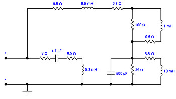
Characteristics of load used for tests

Two kinds of load were used for further testing, pure resistive load – power resistor 4.7ohm/200W, and a R-L-C dummy load that simulates impedance of the 7” SEAS woofer, the dummy load circuit schematics is shown below:

View attachment 279788

R1 and L1 are voice coil parameters, C1 and L2 and R6 represent cone parameters. The mechanical resistance is usually drawn in parallel with mass L2, but from a circuit view this has equivalent Q as my circuit and I have taken an advantage of the L2 intrinsic dc resistance to act as R6.

Though impedance Z of the pure resistive load equals to R and is a simple real number, impedance of the complex load Z is a complex number and must be represented in a 2-dimensional complex plane:

in Cartesian form:
Z = R + jX, where
R = Re(Z) … real part of Z, resistance
X = Im(Z) … imaginary part of Z, reactance

or in Polar form:
|Z| = sqrt(R^2 + X^2) … magnitude of impedance Z
Ø = arctan(X/R) … phase angle, represents phase angle between voltage and current

View attachment 279787

for more basic info on complex notation and complex impedance definition, please visit:


Simulated dummy load impedance is in the further image:

View attachment 279789

The plots show all the discussed impedance components, Re(Z), Im(Z), |Z| and Ø.

As a comparison there is another image with values of impedance magnitude and phase measured on the built dummy load.

View attachment 279790

We can see very good conformance of measured values with simulated values. In this image we can also see EPDR plot, which means Equivalent Peak Dissipation Resistance, and is extremely important for evaluation of complex impedance impact to amplifier output stage, as we shall see later. EPDR plot shows an equivalent resistor value that would represent the same peak power loading as the complex load at the individual frequency. We can see that at 1460Hz, the EPDR = 2.66 ohm, though magnitude |Z| is seemingly benign 7.546 ohm with 45° phase angle.


Class AB amplifier driving resistive and complex load – comparison of peak power, simulation

First, let's assume a class B/AB amplifier driving a 4.7 ohm resistive load

View attachment 279791

As an example, a pair of MJL3281/1302 “200W” transistors is driven from 34Vrms sine source and is supplied from 2 x 55Vdc power supply. The crucial parameter to be investigated is transistor's peak power. The allowed values of peak power are drawn in datasheets as a so called “Active Region Safe Operating Area” (SOA) and the plots show peak value of collector Ic current as a function of collector-emitter Vce voltage and time. The longer the time exposition to peak power, the lower allowed SOA.

View attachment 279792

So, we need to examine SOA in our circuit example for 4.7 ohm load. We need to see Ic as a function of Vce and compare it to SOA boundary from the datasheet. We shall use log scale for both Vce and Ic to make a comparison with the datasheet SOA plot feasible.

View attachment 279793

We can see that peak power is 160W and the Ic(Vce) red plot always remains below the 1s SOA blue boundary plot. So, with 1 pair of MJL3281/1302 200W/15A transistors we should be save with 4.7 ohm resistive load, when supply voltage is 2 x 55Vdc and output voltage is 34Vrms (load power 246W). Frequency of the sine source is unimportant in case we use the pure resistive load and power transistors are fast enough to handle the 20kHz bandwidth.

Now, let's move to the complex dummy load that simulates a single speaker, 7” woofer. This is the circuit for simulation

View attachment 279794

Please note that dc resistance of the dummy load is 6.6 ohm and thus is higher than the 4.7 ohm resistor resistance used in the previous SOA examination. The impedance plots of this load were shown here above.
The impedance plots of this complex load were shown above and we shall concentrate our examination efforts to the frequency where we have lowest EPDR at considerably high phase angle. Both our intuition, when reading the impedance and EPDR plots, and intensive simulation over wide range of frequencies confirm that the frequencies of concerns are near to 1460 Hz. At 1460 Hz, we have impedance magnitude |Z| = 7.546 ohm, phase angle Ø = +45°, but EPDR = 2.66 ohm! So the peak dissipation factor for output transistors equals to 2.66 ohm resistor, with the load that has 7.546 ohm impedance seen in a conventional way.
Let's start a simulation:

View attachment 279795

We can see that transistor peak stress values have changed significantly, compared to the 4.7 ohm resistor load. Vce(peak) = 102.2 V (same), Ic(peak) = 6.2A (much lower), but P(peak) = 231.3W – much higher than in case of 4.7 ohm load, when it was 160W. The key to this behaviour is a phase angle between load current I(load) and load voltage V(load), that results in different P = Vce*Ic instant power values than in case of a resistor load, where resistor current and voltage are in phase. The simulated circuit SOA is now exceeded, the Ic(Vce) red plot jumps above the SOA boundary blue plot. We would need to add one more pair of output transistors, in parallel with the existing pair, to keep the amplifier on a safe side of SOA, with this complex load.

Impact of complex load to distortion

The impact of complex load impedance to amplifier distortion is not quite straightforward when we look at impedance magnitude and phase plots. Measurements of THD+N vs. frequency and THD+N vs. output voltage at 1kHz were done to illustrate it. The A250W4R class AB amplifier was used for these measurements.

THD+N vs. frequency at 7Vrms output voltage

View attachment 279796

We can see that distortion with the complex load is lower except of the area between approx. 200Hz – 1700Hz. At 278Hz, the complex load impedance is purely resistive and equals to 5 ohm. Below 278Hz we can also see the capacitive part of impedance and above 278Hz starts inductive part of impedance. At 1700Hz, magnitude |Z| is 8.3 ohm, EPDR is 3.03 ohm and phase +49°. Above 1700Hz, distortion with complex load is lower than with the 4.7 ohm resistor, though phase is getting high up to +83°. At 1700Hz and above it, the complex impedance might be modelled by a series connection of 5.37 ohm resistor and 0.586 mH inductor. Quite predictable from the dummy load circuit schematics.

THD+N vs. output voltage at 1kHz

View attachment 279797

At 1kHz we have impedance magnitude |Z| = 6.336 ohm, phase = +34° and EPDR = 2.74 ohm. Compared to distortion with 4.7 ohm resistor, the distortion with complex impedance at 1kHz is higher.

The impact of this complex load to frequency response of the amplifier used was negligible.

View attachment 279798

Conclusion

The simulations show high impact of complex loads to class AB amplifier peak power stress of the output transistors. This is in general valid for all kinds of linear amplifiers. The impact of complex impedances to amplifier distortion is not quite straightforward and may be only guessed from the impedance plots. What might be the issue from the point of view of peak power dissipation does not necessarily reflect in high distortion, in case that output devices are not destroyed.
In case of class D amplifiers, when the output transistors dissipate the power mostly during the switching transitions, it is impossible to draw any conclusions from the data I have posted here. Further investigation will be necessary.


Further reading:


__________________________________________________________________________________________________________________________________________

Several hours later - I have just started to test class D amplifiers with the complex load shown in this thread. First on the bench is AIYIMA A07 and the results are worse than I have expected. The amplifier is unable to handle frequency sweep from 20Hz to 30kHz even at low output voltage 3.5V. It is able to manage the stepped sine frequency test, however. Below are the results, frequency response and distortion vs. frequency. To drive a full range speaker with 1 driver, the amplifier would not be usable.

View attachment 279875

View attachment 279876View attachment 279886 View attachment 279887
FuNNy........ How It All Boils Down To the Three most important And all that is electronics,,,,,,, L, C, R, Anbd Timim inbetween them...... :)
 

Head_Unit

Major Contributor
Forum Donor
Joined
Aug 27, 2018
Messages
1,359
Likes
721
The fact is there is no single 'complex' load that would be valid for the majority of speakers out there. One could make some loads that will be very hard for amps but are these realistic ?
- Any complex load testing is more interesting than none is what I say.
- So is lower-than-usual resistive testing, if that's all we can get
- I always thought The Power Cube was great but wished it ran at a more punishing bass frequency like 40 Hz or 70 Hz or something.
- High frequencies I prioritize far less. I've been measuring the spectrum at every concert I go to: a lot of energy up to maybe 500 Hz, then drop-off, then more drop-off. Recorded music surely differs, but I don't think radically.
- In many disciplines, testing is much harder than actual conditions. That's how we learn! :)
 

IPunchCholla

Major Contributor
Forum Donor
Joined
Jan 15, 2022
Messages
1,116
Likes
1,400
- Any complex load testing is more interesting than none is what I say
Only if complex loads issues don’t show up in the already measured 4 and 8 ohm differences, which as far as I have seen, nobody has actually shown.

I think perhaps it could be better visualized by a well scaled difference graph between those two measurements along with a standard for how much deviation might indicate audibility.
 

radix

Major Contributor
Joined
Aug 1, 2021
Messages
1,404
Likes
1,343
What do you think of the Audiophile load, which I think they still use? This article is from 1995.


NTK

Major Contributor
Forum Donor
Joined
Aug 11, 2019
Messages
2,713
Likes
6,001
Location
US East
If one thinks a 4 or 8 ohm resistive load is not representative of "one's speakers" acting as a test load for an amplifier, why should one think some other random reactive loads would be?
 

tmtomh

Major Contributor
Forum Donor
Joined
Aug 14, 2018
Messages
2,769
Likes
8,144
If one thinks a 4 or 8 ohm resistive load is not representative of "one's speakers" acting as a test load for an amplifier, why should one think some other random reactive loads would be?

Exactly. I think some of the concerns about complex loads are important, but I also think that simple dummy load tests can tell us a bit more about this than some folks seem to think. And I can think of two examples:
  1. Frequency Response: For Class D amps and many (most?) tube amps, the frequency range in which the amp's load dependency creates non-flat frequency response will not change with a dummy load vs a complex load. The level of the peak or dip at any given point within that frequency range will of course be different depending on the nature of the load, but an amp that's flat from 20Hz-5kHz with 4 and 8 ohm dummy loads can be expected to also be flat in that same range with a real speaker. And an amp that's flat from 20Hz-20kHz - in other words is load-independent - will remain so with a complex load. (Again, my understanding is that this applies to solid state amps and many but perhaps not all tube amps. Please correct me if I'm mistaken - thanks!)
  2. Power Capacity: There's a legitimate concern about amp capacity at frequencies with a combination of low impedance and difficult phase angle. But since the EPDR measure can account for both of those elements and combine them into a new, single, estimated impedance load, I would say that testing an amp with a simple 2 ohm dummy load can tell us quite a lot about its ability to handle such situations with complex/real loads. In other words, if a speaker is 4.2 ohms at a given frequency but the phase angle produces an EPDR of 2.9 ohms, then a 2 ohm dummy load will tell you whether or not the amp can handle that - you don't need a complex load to test that.
So IMHO, simple loads are quite useful even for understanding or predicting amp behavior with real, complex loads. If you want to buy a sub-$200 Class D amp for budget reasons, then that amp is going to be load-dependent, and I would imagine it would be helpful to know the exact treble frequency response for different models in that category with your speakers. But that's not something anyone can feasibly test (except you, if you have the gear and are willing to buy multiple amps to test). And even there, if @amirm tests two cheap, load-dependent Class D amps with dummy loads and Amp 1 is +2dB/-1dB at 20kHz depending on load while Amp 2 is +4dB/-2.5dB at 20kHz, then you can make an informed decision and get Amp 1, even though you don't know what the real-world, non-smooth FR deviation curve will look like with your speakers.

Similarly, if an amp shuts down when Amir tests it with a 2-ohm dummy load, then you won't know what it will do with an EPDR of, say, 2.7 ohms or 3.3 ohms. You'll only know it's okay into 4 ohms and not okay into 2 ohms. But in that case, does it really matter? If online measurements of your speaker shows its EPDR dips to 2.7 ohms, do you really want to power them with an amp that shuts down when presented with 2 ohms? Do you want to cut it that close?
 

RayDunzl

Grand Contributor
Central Scrutinizer
Joined
Mar 9, 2016
Messages
13,250
Likes
17,191
Location
Riverview FL
What happens when more than one frequency is in play?

Does inductance of the load at one frequency cancel (from the amplifier's view) capacitance at another?
 

NTK

Major Contributor
Forum Donor
Joined
Aug 11, 2019
Messages
2,713
Likes
6,001
Location
US East
What happens when more than one frequency is in play?

Does inductance of the load at one frequency cancel (from the amplifier's view) capacitance at another?
Not when the system is linear. For linear systems (principle of superposition):

Input A -> output X
Input B -> output Y
Input A+B -> Output X+Y

So adding another input signal does not affect the portion of the output from previous inputs.

THD is to measure how nonlinear the system is (i.e. how much it deviates from linear).

[Edit] Note that EQ depends on this principle to work. If you boost or cut the response at one frequency band, it does not affect the other bands (i.e. signal contents at different frequencies are orthogonal).
 

Ron Texas

Master Contributor
Forum Donor
Joined
Jun 10, 2018
Messages
6,234
Likes
9,363
If one thinks a 4 or 8 ohm resistive load is not representative of "one's speakers" acting as a test load for an amplifier, why should one think some other random reactive loads would be?
It's a closer approximation to a real loudspeaker passive crossover than a resistor. Maybe the proposed loads are not so random after all.
 

NTK

Major Contributor
Forum Donor
Joined
Aug 11, 2019
Messages
2,713
Likes
6,001
Location
US East
It's a closer approximation to a real loudspeaker passive crossover than a resistor. Maybe the proposed loads are not so random after all.
Closer? How?

[Edit] For example, this is the impedance plot of Magnepan LRS, from 2 - 40 kHz, the impedance magnitude ranges from 2.9 - 4.1 ohm, with phase from -4 deg to +16 deg.
Is it closer to a 4 ohm resistive load, or to PMA's proposed complex load (see below)?

If we indeed want to test amplifier with a complex load, we will first need an engineering project to study and design this load(s) (that is able to please most people), not some random values.

index.php


index.php
 
Last edited:

MaxwellsEq

Major Contributor
Joined
Aug 18, 2020
Messages
1,745
Likes
2,630
With reactive loads, power amplifiers have to deal with current leading or lagging voltage. Also the power supply needs to handle this circumstance. This can lead to voltage and current excursions which might be outside an amplifier's safe operating area in a way that may not be tested by pure resistance loads. When dealing with very high voltage power distribution in industrial environments with large motors, this sort of thing is an essential part of power device design.

This would obviously be at the extreme upper end of power output, so may not be an issue in the real world.
 

tmtomh

Major Contributor
Forum Donor
Joined
Aug 14, 2018
Messages
2,769
Likes
8,144
When it comes to power capacity of an amp - not frequency response, just power capacity - what would a complex load tell us about an amp's robustness that a 2 ohm dummy load wouldn't?
 

SIY

Grand Contributor
Technical Expert
Joined
Apr 6, 2018
Messages
10,509
Likes
25,338
Location
Alfred, NY
When it comes to power capacity of an amp - not frequency response, just power capacity - what would a complex load tell us about an amp's robustness that a 2 ohm dummy load wouldn't?
Stability. Not an issue usually for most amps, but at the very cheap and very expensive ends of the bell curve, oddball stuff can happen. Three brands on the high end that come to mind are Quatre (long gone), Rappaport (also long gone), and Naim (still hanging in). But for more normal stuff used by 99% of the world, this isn't much of an issue.
And an amp that's flat from 20Hz-20kHz - in other words is load-independent - will remain so with a complex load.
Not necessarily. You can use the voltage difference between 4 and 8 ohm loads to back into the amp's source impedance which will cause frequency response errors. Again, for the vast majority of amps and speakers, this will be a pretty negligible issue, but there's some oddballs out there in the fashion audio and ultra-cheap audio segments.
 

IPunchCholla

Major Contributor
Forum Donor
Joined
Jan 15, 2022
Messages
1,116
Likes
1,400
You can use the voltage difference between 4 and 8 ohm loads to back into the amp's source impedance which will cause frequency response errors.
This is interesting. Can you point me to any articles or specific amps so I could understand the mechanism better?
 

SIY

Grand Contributor
Technical Expert
Joined
Apr 6, 2018
Messages
10,509
Likes
25,338
Location
Alfred, NY
This is interesting. Can you point me to any articles or specific amps so I could understand the mechanism better?
Fred Davis's old articles on cables covered the source impedance issue quite nicely. A little Googling should locate them.

It's actually pretty simple: the amplifier's source impedance forms a voltage divider with the load. If the amp's source impedance is thought of as a constant R (it's not, but close enough for basic understanding) and the load's impedance varies with frequency, the voltage across the load will vary with frequency. You can see this effect in Stereophile's amp measurements with their speaker simulator.
 

IPunchCholla

Major Contributor
Forum Donor
Joined
Jan 15, 2022
Messages
1,116
Likes
1,400
Fred Davis's old articles on cables covered the source impedance issue quite nicely. A little Googling should locate them.

It's actually pretty simple: the amplifier's source impedance forms a voltage divider with the load. If the amp's source impedance is thought of as a constant R (it's not, but close enough for basic understanding) and the load's impedance varies with frequency, the voltage across the load will vary with frequency. You can see this effect in Stereophile's amp measurements with their speaker simulator.
Thanks for the reply. I think I misunderstood your reply to @tmtomh. I took his comment to mean that if an amplifier measured the same (flat) for 8, 4 (and maybe ) 2 ohms it would be load independent. Your scenario would be flat but not the same for 8 and 4 ohm measurements.
 

SIY

Grand Contributor
Technical Expert
Joined
Apr 6, 2018
Messages
10,509
Likes
25,338
Location
Alfred, NY
Thanks for the reply. I think I misunderstood your reply to @tmtomh. I took his comment to mean that if an amplifier measured the same (flat) for 8, 4 (and maybe ) 2 ohms it would be load independent. Your scenario would be flat but not the same for 8 and 4 ohm measurements.
Flat frequency response, but the voltage will change because of the same voltage divider effect.
 
Top Bottom