• WANTED: Happy members who like to discuss audio and other topics related to our interest. Desire to learn and share knowledge of science required. There are many reviews of audio hardware and expert members to help answer your questions. Click here to have your audio equipment measured for free!

ESS datasheet rant

Changed the resistor so that CHIP_EN rises faster than MUTE_CTRL, and indeed it does:

1735921809552.png


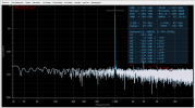
however, the noise did not improve, even got slightly worse. This is now with "coherent averaging" off (edited to the same channel as yesterday):
1735922979357.png


will try to play with the rise time of MUTE_CTRL now....
 
Last edited:
the noise did not improve, even got slightly worse. This is now with "coherent averaging" off:
IMHO the comparison to previous version should be done with same measurement params, i.e. with coherent averaging enabled. The vector averaging suppresses everything not perfectly in-phase with the fundamental.
 
  • Like
Reactions: MCH
Note that the FFT length also has influence on the noise level, as does the windowing function.
 
IMHO the comparison to previous version should be done with same measurement params, i.e. with coherent averaging enabled. The vector averaging suppresses everything not perfectly in-phase with the fundamental.
No problem, i have everything wired up. There you go, and sorry, but not only i hate Cuemix, REW and taking measurements in general, but as it has been made evident, i have absolutely no clue. But i believe now the parameters must be the same i used yesterday.

EDIT: was the other channel sorry :facepalm: here is the one measured yesterday:

1735922831588.png
 
IIUC suddenly the THD is by 3dB better than without the vector averaging :)
 
  • Like
Reactions: MCH
IIUC suddenly the THD is by 3dB better than without the vector averaging :)
out of curiosity, how does it calculate the THD? because without the coherent averaging the most prominent harmonic (3th) is still -118dB
 
It seems OK to me: THD -114 for H3 -118, THD -119 for H3 -121. But best to ask @JohnPM. I may be wrong with the vector averaging, but it always seemed to me that small harmonics drop a bit when enabling it (and it made sense to me by principle).
 
  • Like
Reactions: MCH
Its tempting to think of the pull up resistor node as low impedance because of the time constant capacitor to ground. Such temptation leads to running a long trace on the PCB for convenience if for example, it needs to run to a DIP SW or a resistor array. I fell into that trap once back in the day and had to tack a good quality capacitor from the IC pin to ground to kill noise pickup &/or EMI on the trace.
 
Guys, after a couple more iterations of testing different RC values with no significant effect on noise performance, i decided that the time spent is not worth what it costs to print new PCBs, and on top i can get rid of the jumper and optimize the layout. This was not the initial intention as this was only a way to use a dead corner of another PCB but i guess i am in the rabbit hole now and i have all the parts that i need....

Also, to solve the rising time issue, i am going to use SN74LVC1G17 (Schmitt-Trigger Buffers) in between the RC filter and the pins. They might be not necessary but they cost peanuts and i have plenty of PCB real state on the back (still at 49x26 mm total size). Also, i have never used them before and want to see how they work. This below will be the schematic: (the values of the RC filter are not set, will chose them empirically). One thing that i did observe is that if i set MUTE_CTRL too early on purpose (for instance eliminating the capacitor in the RC filter) the ADC performs like crap, with much higher noise and distortion, so better do what the datasheet says.

1736026345278.png


Also switched to mostly 0603 parts that allows me to place decoupling capacitors closer to the pads of the chip, placed a bunch of vias and routed a bit better the analog inputs (i observed -110dB crosstalk iirc with the current board). Ah, and i added test points :)
 
Ok guys, got the new PCBs:
Added a small pi filter at power in, corrected the error from the datasheet schematic :rolleyes:, that is, no more sketchy jumper, used a couple of buffers to have a nice sharp turn on sequence and routed everything a bit better in my opinion.
New turn on sequence:
1737742392165.png


Installed multitone and used asio4all driver, and here is the result (my very first time with multitone, don't kill me if the settings are all messed up):

1737750673554.png


DescriptionCurrent
TitleADC
VersionMultitone Analyzer v1.1.12
Test Signal1000Hz sine
Test SettingsGain:0dB Tones:1 crest=1.4
Sample RateFs(out): 96000Hz/1 Fs(in): 96000Hz/2
FFTSize:65536 Window:Blackman-Harris 7
AveragesAverages:1 Type:Amplitude Overlap:87.5%
Range20 - 20000Hz
Fundamental-0.5dBFS @ 999Hz
Level0dBFS -5.2dB(rms)
TD+N0dB
IMD-- dB
IMD+N-- dB
THD-120.1dB
Noise-113.3dB -116dBA
N+D-107dB -108.7dBA
SNR112.9dB
SFDR130.7dB @ 17.5Hz
ENOB18.1 bits
Delay-0.4ms
Drift0ppm
Jitter(peak)51.9ps @ 754.4Hz
Jitter(rms)41.1ps
HarmonicsH2:-132.1dB/+127° H3:-121.5dB/+170° H4:-135.9dB/+160° H5:-133.7dB/+10°


And that's it folks, i am more than happy with the result, which i believe matches the specs of the chip (i am not sure about multitone's nomenclature).

I am going to give the folks at ESS and myself an applause, a golfing panther, and a well deserved place in the green section of the ADC ranking. There it goes, thank you guys for your help.

1737744075605.png
 

Attachments

  • 1737741683205.png
    1737741683205.png
    124.4 KB · Views: 32
Last edited:
Just change the dBFS to dBr at Multitone for comparable results.
It looks good!Here's some base settings,load them up and just change the basics to suit you,like sample rate and stuff and choose your own devices:
 

Attachments

  • _MultitoneMCH.zip
    5.1 KB · Views: 13
Last edited:
  • Like
Reactions: MCH
Just change the dBFS to dBr at Multitone for comparable results.
It looks good!Here's some base settings,load them up and just change the basics to suit you,like sample rate and stuff and choose your own devices:
Thanks, when I figure out how to do that, I will update it. Do I need to run the measurements again?
edit: ah cool i see:
1737745580013.png
 
Last edited:
Thanks, when I figure out how to do that, I will update it. Do I need to run the measurements again?
edit: ah cool i see:
View attachment 423568
Just go "file">load settings>point to the uncompressed file and you're done.
You can rerun the measurement just by pressing the reftresh button over the chart or double click it in history,etc.
You can also press the small preview window (the one with the TDN+N result) to see the full table results.
 
  • Like
Reactions: MCH
Adding multitone. Not sure if i have measured it correctly though. Later will test the voltage divider that i included in the board to see if it is detrimental. What other tests could be relevant for ADCs? i am starting to like the multitone app.

1737806114411.png
 
Unfortunately the voltage divider impacts the performance quite a bit (see below) the third harmonic grows significantly and SNR drops.
I used 0603 10k thin film resistors and 0603 100k regular thick film resistors (i did not have thin film of this value). Is there anything i can do to try to improve the results? will all thin film do something?

1737813019725.png
 
Last edited:
The internal PGA has a selectable input impedance of either 2.5k or 10k (I presume between IN_Px/IN__Mx). Why then would you be using 100k/10k passive dividers in the first place?
*cough* loaded voltage divider *cough*
*cough* resistor thermal noise *cough*


The impact on noise is probably even greater than you realize, as I bet you haven't gotten to playing with PGA gain or ARE yet.

I would imagine that the inputs expect to be driven with reasonably low source impedance, even if this design appears to be a lot less demanding than a number of traditional AKM or Cirrus ADCs. Some of your increased H3 may also be a result of this. Having an ADC without a proper input stage sure feels a bit daring to me. It would be a good opportunity to establish some input CMRR if nothing else.

Resistor distortion (due to tempco) tends to be negatively correlated with power handling and hence size, which is particularly noticeable in thick films. Going for tiny 0603s clearly isn't the smartest move in this context, especially if the resistor in the divider's upper leg is the thick film (it sees the bulk of power dissipation). Thick films are best avoided in the signal path in general, they're basically the SMD equivalent to carbon film.

Recommended reading.
 
The internal PGA has a selectable input impedance of either 2.5k or 10k (I presume between IN_Px/IN__Mx). Why then would you be using 100k/10k passive dividers in the first place?
*cough* loaded voltage divider *cough*
*cough* resistor thermal noise *cough*
As mentioned several times, the board works in hardware mode, PGA gain selection is only available in software mode. cough.
The impact on noise is probably even greater than you realize, as I bet you haven't gotten to playing with PGA gain or ARE yet.
ARE is also only available in software mode
I would imagine that the inputs expect to be driven with reasonably low source impedance, even if this design appears to be a lot less demanding than a number of traditional AKM or Cirrus ADCs. Some of your increased H3 may also be a result of this. Having an ADC without a proper input stage sure feels a bit daring to me. It would be a good opportunity to establish some input CMRR if nothing else.

Resistor distortion (due to tempco) tends to be negatively correlated with power handling and hence size, which is particularly noticeable in thick films. Going for tiny 0603s clearly isn't the smartest move in this context, especially if the resistor in the divider's upper leg is the thick film (it sees the bulk of power dissipation). Thick films are best avoided in the signal path in general, they're basically the SMD equivalent to carbon film.
simply put: it was small or nothing. the voltage divider is just an option (via a few jumpers) for convenience to measure the frequency response and basic performance of diy amps i do. Once it is there, if it is a matter of changing for thin film resistors, that's fine, but i am not willing to put opamps there, not this time at least.
thank you
 
Last edited:
Back
Top Bottom