• WANTED: Happy members who like to discuss audio and other topics related to our interest. Desire to learn and share knowledge of science required. There are many reviews of audio hardware and expert members to help answer your questions. Click here to have your audio equipment measured for free!

Does The Inductor, Capacitor or Box Volume Have Most Effect on Impedance?

Trdat

Addicted to Fun and Learning
Forum Donor
Joined
Sep 6, 2019
Messages
968
Likes
397
Location
Yerevan "Sydney Born"
Apologies for the amatuer question, but my woofer in my 3 way DIY speaker drops down to 3.3 ohms and I have two spare amps that I can BTL if it wasn't for the drop in ohms, I can use them as they have more power than my current amp. The woofer driver impedance graph from the manufacturer has it at around 8ohm but I know all that changes.

I dont want to touch the inductor as it is the low pass which is needed for the crossover to the mid woofer but the capacitor is not so important. Can the capacitor have any effect on the impedance or is the box volume more of a culprite?

Is there any way around this drop in ohms for the woofer?
 

mtg90

Member
Joined
May 24, 2021
Messages
56
Likes
141
Location
Illinois
If the impedance is dropping lower then the DCR of the woofer then it is the crossover implementation causing so. The cabinet itself will never cause the impedance of the woofer to drop below DCR.

The inductor by itself in series with the woofer (1st order low-pass) also won't cause impedance to drop.

When you add the capacitor in parallel making it a second order lowpass can you can start to run into problems with low crossover points as the filter will start to interact with the natural low frequency impedance peak/s of the woofer/cabinet. This filter oscillation results in a peak in output and much lower impedance in the range between the crossover and the woofer's resonance.

A drastic drop in impedance can also occur if the capacitor value is oversized for the inductor used or the driver impedance is lower then the low pass was designed for.

Decreasing the value of the capacitor or adding some series resistance can help alleviate the drop in impedance to some degree but results in either a higher crossover knee or a shallower slope. Though if the woofer is 8 ohms a drop to 3.3 ohms sure does sound like the capacitor is oversized for the filter unless it is a very low crossover point you are trying to use.

If it is a low crossover point and not incorrectly sized capacitor the option to best prevent this issue (while staying passive) is to place a parallel RLC network to suppress the woofer/cabinet resonance, this allows the lowpass to function as intended without being influenced by the large large impedance swing at the low end. The downside of this is often the very large component values needed for the filter and some additional energy dissipated by the filter itself.

If you are modeling the crossover through software (Vituixcad, Xsim, PCD, etc.) you should easily be able to see how the impedance is influenced by the filter choice and component values used and try and design around the limitations.
 

Rick Sykora

Major Contributor
Forum Donor
Joined
Jan 14, 2020
Messages
3,613
Likes
7,348
Location
Stow, Ohio USA
If not all, at least the impedance curve and the woofer model info. :)

It is most likely the crossover. Is 3.2 ohms a minima or does it stay that low for a broad range of frequencies? Like to understand how bad the problem is first.
 
OP
Trdat

Trdat

Addicted to Fun and Learning
Forum Donor
Joined
Sep 6, 2019
Messages
968
Likes
397
Location
Yerevan "Sydney Born"
It is, most likely the crossover but I thought that perhaps, it might just be the inductor and capacitor to the woofer not the entire crossover? If its the whole crossover I wont touch it but if it is the capacitor then it wont be a hassle to remove it and wont be doing that much damage to the sound as it is only a high pass right? I can use the natural roll off of the box?

And apologies, I wasn't very clear the speaker is already designed and finished I am seeing if anything can be done, I should have said it in the initial post. Apprecaite aeveryones help, I wont go to any extreme lenghts to change anything if nothing exists plus this is always a learning avenue for me as well.

https://www.scan-speak.dk/product/22w-8534g00/ This is the woofer

I can confirm that with DATS that the impedance is similar to that of the posted graph which is from Troel's DIY page. The speaker is the ScanSpeak Bokshelf 3WC. And the crossover is very low at 350hz.

I can't post the schematic here as it would be wrong to do but I can provide the values for parts for the woofer which is L4 4.70mh and C5 100uf.

Regarding how bad the problem is, between 90ha and 200hz it is under 4ohms with 120hz dropping to 3.3ohms and the Hypex amp in BTL mode says a minimum of 4ohms and recommends above 8ohms.

I know the easieast wll be to purcahse a new amp but to get over 200watts these days with decent SINAD your still paying above $500 US I have two NC122 Hypex amps lying around and in BTL mode I can get more power than my current NC252.

Unfortunately, vituixcad is one thing I haven't learnt yet because i pursued DSP crossovers with Audiolense for my other main system. And the little I do know is limited as there is no ZMA file for the woofer and thats if all I am doing is a line to the driver with a capacitor lol. If I have to simulate the whole corssover then probably I wont be succesful.
 

Attachments

  • sin-imp-final_min_1200.png
    sin-imp-final_min_1200.png
    131 KB · Views: 50

voodooless

Grand Contributor
Forum Donor
Joined
Jun 16, 2020
Messages
10,404
Likes
18,364
Location
Netherlands
Thanks for all the info, that helps a lot!

It is strange though, Troels links the 8R version of the woofer, but looking at the impedance, it looks like the the 4R version. It has exactly the correct low impedance dip:


I don’t see any other way, the filter doesn’t do this.
 

solderdude

Grand Contributor
Joined
Jul 21, 2018
Messages
16,053
Likes
36,440
Location
The Neitherlands
The 4Ω woofer is spec'd:
Nominal impedance
Z 4Ω
DC resistance RE 3.0Ω

for 8Ω = DC resistance 5.9Ω

So if the 4 ohm version is used the impedance can dip to 3 ohm even without a filter.

The filter is quite low (230Hz) and right at the dip in the impedance of the woofer so even the 8Ω woofer + filter could dip below 6Ω
 
OP
Trdat

Trdat

Addicted to Fun and Learning
Forum Donor
Joined
Sep 6, 2019
Messages
968
Likes
397
Location
Yerevan "Sydney Born"
Thanks for all the info, that helps a lot!

It is strange though, Troels links the 8R version of the woofer, but looking at the impedance, it looks like the the 4R version. It has exactly the correct low impedance dip:


I don’t see any other way, the filter doesn’t do this.
Yes, it does. I must have looked at a different or wrong graph. Damn, okay then there is nothing we can do if that is the case. It was worth a try.

But, then again I am little confused to what version of the driver I do have, I am convinced that it is the 8ohm. Below is Madisounds graph and it doesn't dip below 7ohm and is the same 8534G00

I have to pull it out and check but there should be no reason I have been sent or all this time not realised that it is a 4ohm version.
 
OP
Trdat

Trdat

Addicted to Fun and Learning
Forum Donor
Joined
Sep 6, 2019
Messages
968
Likes
397
Location
Yerevan "Sydney Born"
The filter is quite low (230Hz) and right at the dip in the impedance of the woofer so even the 8Ω woofer + filter could dip below 6Ω
So the question remains if I do have the 8ohm version can it dip to 3.3ohm?
 

Geert

Major Contributor
Joined
Mar 20, 2020
Messages
1,955
Likes
3,570
If all you have in series with the woofer is one inductor, than just measure the DC resistance on the connection terminals of the speaker box with a multimeter. Should be sufficient to indicate which version of the woofer you have without pulling it out.
 

Rick Sykora

Major Contributor
Forum Donor
Joined
Jan 14, 2020
Messages
3,613
Likes
7,348
Location
Stow, Ohio USA
Am not seeing any major issue here. Would expect properly mounted Hypex amps to handle this speaker load bridged. They are thermally protected and should shut down if overdriven. See nothing here that is not expected and nothing worthy of redesign. Ofc, this all is based on having used the 8 ohm woofer and having implemented the design correctly.

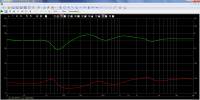
Just as Troels measurements show, the woofer filter does lower the overall system impedance. This can be readily modeled in VituixCAD even using the simple default (purely resistive) 8 ohm driver...

1695462932614.png
 
Last edited:
OP
Trdat

Trdat

Addicted to Fun and Learning
Forum Donor
Joined
Sep 6, 2019
Messages
968
Likes
397
Location
Yerevan "Sydney Born"
Am not seeing any major issue here. Would expect properly mounted Hypex amps to handle this speaker load bridged. They are thermally protected and should shut down if overdriven. See nothing here that is not expected and nothing worthy of redesign. Ofc, this all is based on having used the 8 ohm woofer and having implemented the design correctly.

Just as Troels measurements show, the woofer filter does lower the overall system impedance. This can be readily modeled in VituixCAD even using the simple default (purely resistive) 8 ohm driver...
Thanks Rick, appreciate the response. I am confident the design has been implemented correctly and my dats impedance graph is exactly the same as the posted one by Troel, that should give us enough to know that all being equal everything is the same.

I checked, the driver it is definetely the 8ohm driver.

I also just in case have added, the NC122MP documentation which explains the BTL configuration on page 17.

I will give it a try, but I have one remaining question does the input sensitivity change in BTL configuration? I ask this because the input sensitivity on the NC122 is obviously less than the NC252 but with more power I would reach more wattage with less input so it evens out right? My Marantz AV7005 pumps out as you all know up to 6 volts around 0 DBFS volume, I get clipping hence why I want more power.

Anyway, this is great news if you think that the Hypex should handle it.
 
OP
Trdat

Trdat

Addicted to Fun and Learning
Forum Donor
Joined
Sep 6, 2019
Messages
968
Likes
397
Location
Yerevan "Sydney Born"
It's like when you take your mum's V6 Camry out and realise how gutless your 4 cylinder really is.

Its working great, I just hope damage to the amp does't eventuate, but if there is a thermal protection it should it shut down.
 

Rick Sykora

Major Contributor
Forum Donor
Joined
Jan 14, 2020
Messages
3,613
Likes
7,348
Location
Stow, Ohio USA
So, to answer your original thread title, it depends at which frequencies you consider. :)

Certainly, there is potential for any speaker part to cause a major change in impedance. In this design, the atypical aspect is the aperiodic vent as it lowers the bass impedance significantly around the bass resonant frequency. Otoh, the woofer filter impedance dip around the crossover is pretty common.

Thanks for sharing as is interesting from a design perspective. Am going to use it add further examples to my Understanding Sealed Speaker Impedance thread. :cool:
 
Last edited:

Rick Sykora

Major Contributor
Forum Donor
Joined
Jan 14, 2020
Messages
3,613
Likes
7,348
Location
Stow, Ohio USA
Since it is specific to the design, here is the impedance of the same woofer in a more typical bass reflex enclosure...

1695848633785.png


Note how much higher the resonant peaks are compared to the aperiodic vent used in your speaker.
 
Top Bottom