• WANTED: Happy members who like to discuss audio and other topics related to our interest. Desire to learn and share knowledge of science required. There are many reviews of audio hardware and expert members to help answer your questions. Click here to have your audio equipment measured for free!

Does Phase Distortion/Shift Matter in Audio? (no*)

First, those cork screws:
1730012570101.png

The one of the left shows the phasor, meaning the complex value at t=0, with its development in time e^(iwt) appended. This is not a wave travelling through space, this is simply adding on a trivial term that is anyway divided out in a transfer function, as it is found in both the input and the output. That is why a signal, when assuming sinusoidal steady-state behavior, can be written as complex number with magnitude and phase only.
The one on the right has a frequency axis, not a time axis, and again, this is not hurtling through space. This shows exactly the phasor part, at each frequency, without the above-mentioned time dependency. This is just a more difficult-to-read version of magnitude and phase, and holds no more or less information than that.

Second, I am not saying that the physics is not contained in the transfer function, i.e. real and imaginary parts, or magnitude and phase. It certainly is. When you measure a loudspeaker, and relate your findings back to input voltage, then that voltage is the reference, and so measured phase is relative to that. That phase (and magnitude) is a consequence of the electromechanical setup of the transducer and the coupling between the structural mechanics and the acoustics. If there is wave propagation involved, as there would be here, it may or may not be contained in the phase, as the user will have to click, or not, on a setting regarding how far away the loudspeaker is.

However, a wave is a global abstraction, whereas the measurement signals are in points. There is no immediate need for thinking about waves, when learning signal processing. That is why most introductary chapters are called Signals and Systems, with no mention of physics. If you only try to learn via physics/measurements, you will never understand why compled numbers, negative frequencies, and complex conjuation, have to be introduced as soon as you talk signal processing.

If you don't understand the fundamentals of signal processsing, you are probably lacking in other places too, and I see many projects being cancelled, just because the engineers could not succeed with understanding why the test keeps failing, and if only the basics were in place, you would be able to quickly pinpoint at which point things start to break down regarding for example certain assumptions you have made, that do not actually hold, or whatever the case may be. There is only the hard way of studying way beyond your formal education to get deep into all of these aspects.

Things can go really wrong if you for example think that a driver will always produce postive pressure for positive displacement. I saw a phd level employee think this at a former workplace, which was leading to a remedy for feedback stability that would have made everything worse, not better. This situations come up all the time, but if nobody is there with proper knowledge, it will be written of as "oh, we know simulations and measurements never match", which is of course nonsense.
 
Things can go really wrong if you for example think that a driver will always produce postive pressure for positive displacement. I saw a phd level employee think this at a former workplace, which was leading to a remedy for feedback stability that would have made everything worse, not better. This situations come up all the time, but if nobody is there with proper knowledge, it will be written of as "oh, we know simulations and measurements never match", which is of course nonsense.
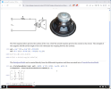
People would be surprised at how often the people you'd think should know better make this kind of mistakes. Here is an example from a Wolfram Mathematica control systems design tutorial video.

They showed a model of a loudspeaker driver, and derived the transfer function from the voltage input, v_in(t), to the diaphragm displacement, x(t). And here is where they got it wrong. Sound pressure is directly related to the diaphragm acceleration, not displacement!
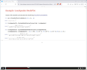
mathematica_controls_loudspeaker_1.png

They then proceed to implement a closed-loop motion feedback control system using a PD (proportional-derivative) controller to control displacement.
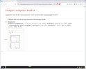
mathematica_controls_loudspeaker_2.png

Here is the Bode plot of zero feedback gains (which is the same as the open loop system). You can see that the system is mass dominated starting at ω < 100, where the displacement (diaphragm excursion) is decreasing with frequency at a slope of -40 -12 dB/octave. You want to operate your loudspeaker driver in the mass dominated region where the displacement response is -40 -12 dB/octave with frequency! That's where you get a flat sound pressure frequency response!
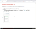
mathematica_controls_loudspeaker_3.png

They dial-in the PD controller gains (k and τ) so that the diaphragm displacement has a flat frequency response to ω > 1000. Which is exactly the wrong thing to do!
mathematica_controls_loudspeaker_4.png
[Edit] Corrected the slope errors.
 
Last edited:
They dial-in the PD controller gains (k and τ) so that the diaphragm displacement has a flat frequency response to ω > 1000. Which is exactly the wrong thing to do!
View attachment 402039
Yeah, this is certainly a strange request for a driver being inherently mass-controlled in a large part of its operating frequency range ;-). They should have chosen the transfer function for acoustic output (same order and complexity level) and gone for that being flat. But to be fair, I think it is worse when such things are not understanding in an audio company than in a mathematics software company. But this is just a snippet of what is going on.

I have the aforementioned PhD engineer show the real part of a response only, because he thought that was the physical one. Sure, we deal with real signals and systems, but here you have to understand that the real projection changes with time, such that magnitude (and phase) is what is important to view.

Measurement systems were checked for days or weeks because it could not be understood how a lowpass filtered square signal could ever have a higher amplitude than the original square signal, leading to overloading of the input, because basic Fourier decomposition was not on anyone's mind.

And oftentimes, much more scattered issues on top of each other, with 'understanding' being based on company chatter, "we had an expert employee once who told us this was right, so this is how we do it', 'this has always worked this way (yes, because you always work with this size/frequency range/application, but not in general)', and just a mixture of intuition, measurements, some correct assumptions, some incorrect, poor documentation, and so on. It can be exhausting to clear this up as a normal employee with no mandate to change anything. Much better to work as a consultant! :)
 
"we had an expert employee once who told us this was right, so this is how we do it"
Many years ago I was designing an update to a portion of an existing system. I had the full specifications for the existing system, and I came across a parameter there that had been set to a particular fixed value without explanation. The designer of the existing system was still at the company, so I asked him why that parameter value was what it was. He answered that it had been set to that value in an earlier system, so he just copied the value. Well, the designer of that earlier system was also still at the company, so I asked him the same question, and got the same answer. To make a long story short, I traced the parameter value back through 25 years' worth of systems, and (believe it or not) I was able to find the original designer. His answer to my question was, "I didn't have time to investigate what the optimal value was, so I just set it to what I thought was a reasonable value, and planned to optimize it later."
 
Many pitfalls indeed for those who try to intuit their way through signal processing and physics. Just getting the point across that a polarity flip is a 180 degree phase shift without being a time delay can be a hassle in engineering departments.
That's a great example. I don't know why they would intuit a polarity flip as a time delay. It's like intuiting that if you inverse the colors on an image, the image has to also move in some direction.
 
That's a great example. I don't know why they would intuit a polarity flip as a time delay. It's like intuiting that if you inverse the colors on an image, the image has to also move in some direction.
I find those "why's" very interesting, as they help me write articles clearing up these issues. For this case, I am pretty this stems from 1) drawing a single frequency sinusoidal always and 2) not wanting to deal with phase being anything other than a time shift. They slide another such sinusoidal of the same frequency along the time line, see when it is opposite in amplitude and then say that since a particular time delay creates a 180 degree phase shift, a polarity flip cannot also be a 180 phase shift, since it has no time delay. This reasoning makes some sense, until you realize that you have painted yourself into a corner by only considering one frequency. At a few frequencies (out of an infinite continuum of frequencies), a time delay will indeed have a magnitude of 1 and phase 180 deg, but the polarity flip has that at all frequencies. It is your drawing instead of calculating that caused the issue. And, even at those frequencies, the system behavior is only the same steady-state, so starting up an input signal at one of those frequencies will not give the same transient response.

For any system that has non-linear phase even to the slightest, there is suddenly several time delays that need to be defined, so it is much better to deal with phase as it contains all of that information.
 
Just getting the point across that a polarity flip is a 180 degree phase shift without being a time delay can be a hassle in engineering departments.
One thing that I see a lot is people who believe that the "phase knob" on a sub alters the phase by the prescribed amount independent of frequency. That's always fun to explain.
 
One thing that I see a lot is people who believe that the "phase knob" on a sub alters the phase by the prescribed amount independent of frequency. That's always fun to explain.
Yeah I would imagine it is done by all pass filtering, but at least for a sub the frequency range is quite limited so perhaps not the biggest of consequence…
 
I don't know why they would intuit a polarity flip as a time delay.
The surprise for me was not that a 180° phase shift involves no time delay; it was that the impulse response of a 180° phase shift (as opposed to a simple sign reversal) does not have pre- and post-ring of infinite extent. This was based upon the fact that a 180° phase shift could be thought of as a Hilbert Transform applied twice, each of which exhibits pre- and post-ring of infinite extent. It was not until it was demonstrated to me explicitly that the ringing cancels-out for the 180° case (though not for any others), that I understood. I'm not ashamed to say that I try to learn something new every day.
 
A 180 degree phase shift at all frequencies is indeed that same as a sign reversal.

All the complex amplitudes (phasors), one for each frequency, are 'rotated' 180 degrees in their phase part. A complex number C1=a+ib=|C1|*exp(i*theta) is linked to its sign reversed version as C2=-C1=-a-ib=|C1|*exp(i*(theta+pi)). So no ringing can be added, as all but the sign is the same as the original signal.
 
One thing that I see a lot is people who believe that the "phase knob" on a sub alters the phase by the prescribed amount independent of frequency. That's always fun to explain.
I was one of those people who thought it prescribed phase independent of frequency, and it was a mystery to me. How could it do that, and why do that? My Behringer digital crossover had phase adjustment on each channel. I would try moving it around but never could hear or measure any effect. There was also a polarity flip setting and that definitely changed things as expected. The time delay worked as expected. I still don't know what the phase adjustment did, or when or how to use it.
 
So no ringing can be added, as all but the sign is the same as the original signal.
If C1 = a + ib = |C1|*exp(i*theta), then if C2 is C1 phase-shifted by pi/2 we get C2 = |C1|*exp(i*(theta+pi/2)). By your argument, no ringing can be added because a "cosine" is simply changed to a "sine". Yet we know that a Hilbert Transform impulse response has ringing of infinite extent in time.

You have presented a frequency-domain example and used it to infer a time-domain phenomenon.
Well, you said you applied it twice, which gives a sign change, right. So what do you mean by "impulse response of a 180° phase shift vs as opposed to a simple sign reversal"? Just curious.
 
So what do you mean by "impulse response of a 180° phase shift vs as opposed to a simple sign reversal"? Just curious.

The impulse of a 180 degree phase shift for all frequencies IS a sign reversal, in that it is a convolution by -1, rather than1 (no phase shift).
 
The impulse of a 180 degree phase shift for all frequencies IS a sign reversal, in that it is a convolution by -1, rather than1 (no phase shift).
That is also what I would say... I am just trying to see if I am missing something. Sometimes a forum like this is too limited to convey the message in full, and what may come off as incorrect just needs some more clarification. I enjoy your posts, btw.
 
So what do you mean by "impulse response of a 180° phase shift vs as opposed to a simple sign reversal"?
Simple. A sign reversal is, of course, just multiplication by -1. A 180° phase shift can be thought of as 180 1° phase shifts, or 90 2° phase shifts, ... , or two 90° phase shifts, or one 180° phase shift. Since a 90° phase shift is a Hilbert Transform, it was convenient to use that for the next part of the thought experiment. The impulse response of a Hilbert Transform has pre- and post-ring that extends to ±infinity in time. So it was logical to conclude that the impulse response of two Hilbert Transforms would also extend to ±infinity in time. But it turns out to be a special case, in which all of that ringing in the impulse response cancels, resulting in a simple sign reversal. That is what I did not realize until it was demonstrated to me explicitly.
 
Simple. A sign reversal is, of course, just multiplication by -1. A 180° phase shift can be thought of as 180 1° phase shifts, or 90 2° phase shifts, ... , or two 90° phase shifts, or one 180° phase shift. Since a 90° phase shift is a Hilbert Transform, it was convenient to use that for the next part of the thought experiment. The impulse response of a Hilbert Transform has pre- and post-ring that extends to ±infinity in time. So it was logical to conclude that the impulse response of two Hilbert Transforms would also extend to ±infinity in time. But it turns out to be a special case, in which all of that ringing in the impulse response cancels, resulting in a simple sign reversal. That is what I did not realize until it was demonstrated to me explicitly.
Sure, you can come up with some non-causal, non-realizable operations that together give you a 180 degree phase shift, as two Hilbert transforms. But the end effect of this IS a sign inversion, as @j_j also says, so I fail to see the difference. But okay, if that brought you some insights, then great.

I think a better example of cancellation is to actually have a summed system, instead of the multiplication of two system in series as the Hilbert transforms, such as the transfer function (s+w0)/(s+w0), where the parts each have infinite impulse response, but the sum of parts has a perfect impulse response.

Anyway, I might have derailed the thread enough with signal processing, when the topic was on audibility of phase ;-)
 
Anyway, I might have derailed the thread enough with signal processing, when the topic was on audibility of phase ;-)

Which may or may not be audible to some skeptics, but the converse, that it is NEVER AUDIBLE, is completely controverted by a simple matlab script. So we must discard the idea that it is NOT audible, so long, and goodbye. That claim is dead, dead, dead.
 
Back
Top Bottom