• WANTED: Happy members who like to discuss audio and other topics related to our interest. Desire to learn and share knowledge of science required. There are many reviews of audio hardware and expert members to help answer your questions. Click here to have your audio equipment measured for free!

Distortion measurement VS driver diameter/frequency

Plcamp

Addicted to Fun and Learning
Joined
Jul 6, 2020
Messages
860
Likes
1,319
Location
Ottawa
IIRC, Earl Geddes mentioned in some interview or lecture that under 700hz , our perception of details/direction etc slowly fades down to the sub bass
so wouldn't trying to match directivity sub 700hz get less and less important with frequency ?
This relates to wavelength of sound. As freq decreases, your ability to distinguish direction decreases…when you get to about 80 hz, the wavelengths are so long you can’t distinguish at all.

One ‘rule’ is that two drivers can be crossed at an indistinguishable frequency (you can’t hear the difference in their location as one driver takes over from the other) if they are separated by no more than 1/4 wavelength Center to Center. If you were crossing a 15” woofer out, you might pick an 8” driver crossed in at 300 hz, because those two drivers can be spaced within 1/4 wavelength at 300 hz or lower. You can see quickly this 1/4 wavelength spacing ideal runs out of steam at higher frequencies, and that’s a key reason you see fullrangers and coaxials.

So, given you want to cross to smaller drivers to maintain dispersion control across all frequencies…you are also constrained on separation of drivers vs size as you choose what to do.
 

puppet

Senior Member
Joined
Dec 23, 2020
Messages
446
Likes
284
Tried as much as i could, perhaps not searching for the correct terms ... excuse me if this is something that was discussed or could've been easily found . :)

I've read multiple times, in many different places ( interwebs ) with different sauces, something that would read similar to this :

" A 6" mid-woofer will have much better lower to middle MIDRANGE than a 12" or 15" driver "

I can use logical deduction and think that perhaps, the mass of the larger drivers could be some limitation at the higher points of that range ?
That feels kinda intuitive .

But then, i thought about distortion.

So my question here ( please bear with my difficulty of phrasing this correctly ) would be :

Shouldn't we be able to see a difference in measured distortion ?
Is this even something that we can measure ? Wouldn't a driver that gets slowed down by a to large mass start to deform the waves at the higher frequencies and thus produce higher distortion ?


Let's set a simple example to help here if i may....

If we compare a 15" and a 6" driver at 1500hz , both at the same SPL let's say 90db . If both exhibit the same amount of distortion ( let's assume it is quite low and all seems fine ) ,
should we assume that the 15" would be as suitable to deliver the same sound quality than the 6" ? ( for the sake of the situation, let's forgo all the directivity and other details please )

If any of you could take a few moments to set my brain in the right direction here, would be greatly appreciated :)

Merry Xmas/holidays all of you !!!
Health and Happiness to you all !!
I'm thinking that by jumping to the premise of distortion being the difference you have disregarded your initial thought ... the difference between the drivers' individual parameters. Mass of the diaphragm, including voice coil and air load, being one ... but include suspension compliance and the resistance of the suspension losses. Clearly, these difference add up to what a 15" vs 6" driver will sound like at 1.5khz. I don't believe harmonic distortion is that different between each example.
 
OP
JeanKazamer

JeanKazamer

Member
Joined
Sep 12, 2021
Messages
61
Likes
31
Clearly, these difference add up to what a 15" vs 6" driver will sound like at 1.5khz
The thought behind asking about distortion is that i believed ( not sure now so please enlighten me ) that all this would show up on distortion measurements ?

If a driver has a hard time doing a smooth cycle because of the required speed Vs its mass let's say, or the stiffness of his suspension , wouldn't that end up causing some measurable distortion ?

You can see quickly this 1/4 wavelength spacing ideal runs out of steam at higher frequencies, and that’s a key reason you see fullrangers and coaxials.
yeah i totally forgot about that ..thanks for pointing it out :) so this adds up to the list as well

@tmuikku unsure i even know what to do with your crumps at this point ...if that gives you an idea of how n00b i still am :)

But i 100% agree that reading, discussing, typing ... best way to learn fast . Specially when discussing with others that have many years of experiences.
 
OP
JeanKazamer

JeanKazamer

Member
Joined
Sep 12, 2021
Messages
61
Likes
31
Forgot to mention the following ...

i am trying to learn more about cone breakup and beaming in relation to driver diameter and materials etc... quite large topic but also really interesting.
If you guys have some good material i could crunch on when i get few free minutes :)
 

puppet

Senior Member
Joined
Dec 23, 2020
Messages
446
Likes
284
The thought behind asking about distortion is that i believed ( not sure now so please enlighten me ) that all this would show up on distortion measurements ?

If a driver has a hard time doing a smooth cycle because of the required speed Vs its mass let's say, or the stiffness of his suspension , wouldn't that end up causing some measurable distortion ?
I'm not sure what else to add except that direct radiators are designed for specific acoustic tasks .. like a subwoofer design will differ from that of a tweeter. Each requires a different set of design parameters ... none of which should induce distortion within their individual defined range but they do have different acoustic characteristics. I'd imagine that a design intended for a specific use and prone to distortion as a result of it's designed parameters, is broken. Typically, distortion issues show up in the lower range of a drivers designed limits or if it is asked to produce an amplitude outside of the designed power range.

To your other request .. from Lynn Olson:
http://www.nutshellhifi.com/library/speaker-design2.html
 
OP
JeanKazamer

JeanKazamer

Member
Joined
Sep 12, 2021
Messages
61
Likes
31
Appologies if i take some time between replies, lots to do daily ( with added Escape from Tarkov wipe :cool: ) Homeschooling the kids, house chores and lots of coming projects i have little time to work on this learning experience .

Thanks for input, i have gone through your link, without understanding it all , most was in a simple enough way that i could understand and make links .
Appreciated .

The intended range ( manuf ) of X driver is def something to consider . Looking at different manuf i've seen large woofers with 500hz to 5Khz list on a 15" unit that def
showed some crazy behavior starting only from 1.8khz and was going downhill from 2.5khz so unsure why they would even mention 5KHz on there lol


Do most of the driver problematic areas show up in the impedance curves ? I can def link the small bleeps to other graphs most of the time be it distortion, waterfall, response etc..


Then about frequency bands ...

Wouldn't a single driver that covers something like 700hz up to 10~12khz be preferable to crossing from a tweeter in the 2-3khz region ?

I don't recall many commercial loudspeakers that use that kind of setup, so there are probably a few reasons why that are out of my knowledge,
if any of you could please explain would be awesome :)

I'll try and look around for more learning on beaming/directivity between woofer and HF units and how the driver diameter players into this.
 
OP
JeanKazamer

JeanKazamer

Member
Joined
Sep 12, 2021
Messages
61
Likes
31
something more if i may

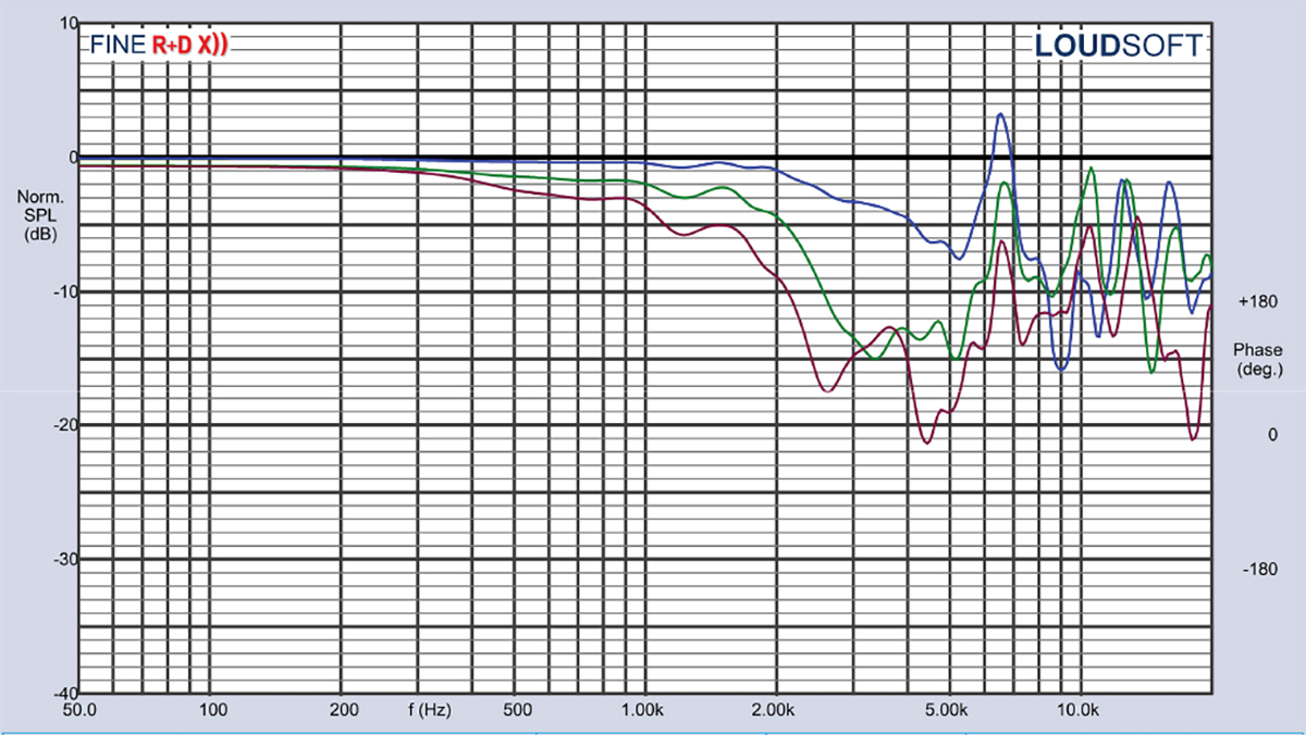
20220425222758_Figure13-Wavecor-WF275BD01-Woofer.jpg


10" driver iirc ... normalized 15-30-45 off axis plot

so when we look at data like this, can we use it to conclude that this driver would be difficult to use at anything higher than let's say 2Khz
because by then the 15deg ( 30deg main cone ) is starting to loose pressure consistency ?

Even the 60deg cone ( +-30deg ) starts getting off from 1.5khz and on

This is directly related to driver diameter right ?
So a smaller diameter driver will exhibit the same " beaming " at a higher point than a larger one
And this is what needs to be " directivity matched " against the next driver in line at the crossover point ?
 
OP
JeanKazamer

JeanKazamer

Member
Joined
Sep 12, 2021
Messages
61
Likes
31
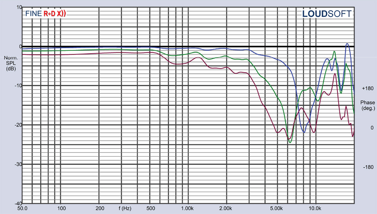
20220218071921_Figure12-E150HE-44-Dayton-Audio-Epique.jpg

5.5" driver for comparison .. so now the same behavior has been pushed up to around 3khz ?
 

puppet

Senior Member
Joined
Dec 23, 2020
Messages
446
Likes
284
Most of your assumptions are correct. Aside from the directivity match, you need to address the cone breakup (as in the 10" graph) or stay away from it. As you probably noticed, the 5" looks to have a bit more room to work with as far as a xo to the tweeter. Most designs that use a waveguided tweeter will look at the -6dB in the off axis measurements to get a feel for where the xo may be best suited as far as a directivity match is concerned. Other designs might want wider directivity and will xo at or near a -3dB off axis point. In that case you're looking at using more drivers/ways to cover the overall frequency range (20-20khz). Lot's of compromise goes into the end result.
 
OP
JeanKazamer

JeanKazamer

Member
Joined
Sep 12, 2021
Messages
61
Likes
31
Thanks for the feedback . So the major breakup for the 10" would be the jump at ~ 6.5khz and 11~12khz for the 5.5" ?
Unsure someone would want to use the 10" at higher than 2-3K neway right ? Having a massive loss of db already at only 15deg must be quite bad lol


Another thing i wanted to ask about for a while,
the waveguides that are shorter vertically than horizontally, do they " redirect " more of the power to the horizontal plane ?
Within its working range of frequency , a WG/Horn provides a pressure boost by limiting the space right ?

Having a shorter sweet spot angle for vertical directivity sounds quite good .
 

Plcamp

Addicted to Fun and Learning
Joined
Jul 6, 2020
Messages
860
Likes
1,319
Location
Ottawa
So the major breakup for the 10"
One thing you can look for is the impedance plot of the driver, looking for any frequencies where it is perturbed as an indicator of breakup behaviour needing treatment. A fairly recent paper by Purifi highlighted that intermodulation distortion can rise at subharmonics of such frequencies, and equalization won’t help.

My 15” woofers are a good example, see the response peak at 1.3khz corresponds with an impedance blip.

So I want to avoid using this driver anywhere near 1.3kHz, plus I might need a series notch filter at that frequency to suppress IM at subharmonics of it.
83BDC834-356A-44BF-93A7-E745CEDFBEFC.png
 

Plcamp

Addicted to Fun and Learning
Joined
Jul 6, 2020
Messages
860
Likes
1,319
Location
Ottawa
Wouldn't a single driver that covers something like 700hz up to 10~12khz be preferable to crossing from a tweeter in the 2-3khz region ?
IMO a single driver that can cover the entire voice range of about 300 to 6 kHz would be best. The only such animal I have so far discovered that can meet that with smooth dispersion performance is a coax compression driver mounted in a 300 hz (big) horn.

 
OP
JeanKazamer

JeanKazamer

Member
Joined
Sep 12, 2021
Messages
61
Likes
31
My 15” woofers are a good example, see the response peak at 1.3khz corresponds with an impedance blip.
Yes that is exactly what i have deducted from looking at many impedance graphs ..always a correlation between those small bumps
and some problems in other measurements .
So i will keep this in mind while looking at different drivers from now on. thanks :)

IMO a single driver that can cover the entire voice range of about 300 to 6 kHz would be best. The only such animal I have so far discovered that can meet that with smooth dispersion performance is a coax compression driver mounted in a 300 hz (big) horn.
from 300 to 6K ? damn .. lol

I had some quick look at B&C coaxials compression drivers

Have you seen this one : DCX50

16_29_02_965_SPL_sito.PNG


The impedance plot looks unusually flat compared to most others :

16_29_02_983_IMP_sito.PNG

So the limitation here is more the size of the horn/assembly than anything else ?
Interesting things though , i'd really like to try a compression driver/horn setup at some point ... I have a pretty large CNC and good enough with 3d/cad stuff to model and cut a very large complex horn if i can get the curves/geometry from somewhere and i believe i've seen a few diy guys that seem to sell this service .

ES-290 Biradial Horn

Introduction The ES-290 Biradial Horn is a direct competitor to the classic Yuichi A-290. The ES-290 takes all that's great about the much loved A-290 and improves many aspects to it's overall performance. ES-290 Flare Geometry A-290 Flare Geometry The complete wrap-around geometry... josephcrowe.com

Ah you are from Ottawa ? Isn't Joseph also from around there ? I've watched all his Tubes . I love Ottawa region . I'm at approx 3 hours east of you :)
 

Plcamp

Addicted to Fun and Learning
Joined
Jul 6, 2020
Messages
860
Likes
1,319
Location
Ottawa
Top Bottom