• WANTED: Happy members who like to discuss audio and other topics related to our interest. Desire to learn and share knowledge of science required. There are many reviews of audio hardware and expert members to help answer your questions. Click here to have your audio equipment measured for free!

Class 1 Measurement Microphone 1/2", 1/4" vs class 2 calibrated

Joined
Oct 5, 2022
Messages
83
Likes
103
I don't disagree with any of that. I do know my Umik has an individual cal file as I have looked at the file for others and they differ. Someone said at one time miniDSP used a single file for all mikes. I don't know when that changed, but I don't think it true now.

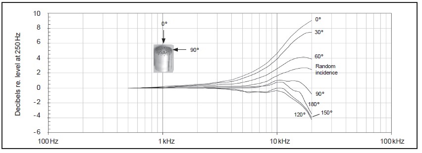
Measuring indoors you have to be picky, picky, picky about exact placement to compare two microphones. Tiny differences alter those upper frequencies.

Electrostatic actuators would be the way to go, but I'm guessing they are rather expensive.

The EMM6 has individual calibration files that you download with your serial number as well.

Microphone placement is also critical when measuring outdoors or in an anechoic chamber due to diffraction of the enclosure and phase differences between drivers. That's why when I was comparing my mics I used a small 20mm tweeter set flush in a large baffle, and I did a gated measurement. That eliminates the room and baffle diffraction.
 

dasdoing

Major Contributor
Joined
May 20, 2020
Messages
4,301
Likes
2,770
Location
Salvador-Bahia-Brasil
isn't it that all those cheaper mics use those cheap Panasonic capsules? Even my SPL meter has one of those.
the diferences are in the quality control. or probably the capsules are tested after manufactioring and divided into tiers with diferent prices
 
Joined
Oct 5, 2022
Messages
83
Likes
103
Awesome. Thanks for describing your rig.
Sounds like we are doing things very similar.

Although i don't hoist the speaker up. I have a deck about 12 ft off the ground, and either set the speaker & spinorama on a 3ft high acoustically inert barrel, or on top of 4ft high subs.
And yep, same thing as far as clipping two sets of guy wires in place, then standing the mic pole up, and clip the third.

It's hard to believe how close the two Beh mics i have, measured to each other. I ordered three more today and don't expect the same luck. But I can easily build calibration files to get them to match up (if even I care to do so.)

here's a pict of the painters pole taken from standing on the deck. Tomorrow I'll put the mic mounts on, and run/secure the XLR cables.
I'm thinking I'll have almost 30ms refection free.
View attachment 235645
Neat, thanks for the pic! I have a picture of my pole setup somewhere, although I'll never find it!

Aren't you concerned about reflections from the deck? I put both the speaker and mic on the pole to get both away from reflective surfaces.

The last speaker I designed was intended to go against a wall, so I just did all the measurements with the speaker facing up on a huge concrete pad. That worked out amazingly well.
 
Joined
Oct 5, 2022
Messages
83
Likes
103
isn't it that all those cheaper mics use those cheap Panasonic capsules? Even my SPL meter has one of those.
the diferences are in the quality control. or probably the capsules are tested after manufactioring and divided into tiers with diferent prices
When I posted my mic measurements at diyaudio a few years ago, Demian Martin had this to say:

"The Earthworks originally used selected Panasonic capsules. They have changed since Panasonic got out of that business. The similar resonances in the plot suggest they may be the same capsule (my guess is a Primo). Earthworks selects and pre-ages their capsules to get stability and maximum flatness and then some electronic tweaking so they do bring a lot of value. Unfortunately the next step from the ECM capsules for precision measurements are the metal diaphragm capsules (like B&K) and those cost quite a bundle.

I use the ECM mikes for day to day measurements and they work fine. i have an extended set of B&K's but I use those for special tests and calibration efforts. They are too expensive and too involved to risk on day to day testing."

I personally was confused about his comments on the resonances.
 

gnarly

Major Contributor
Joined
Jun 15, 2021
Messages
1,035
Likes
1,471
Neat, thanks for the pic! I have a picture of my pole setup somewhere, although I'll never find it!

Aren't you concerned about reflections from the deck? I put both the speaker and mic on the pole to get both away from reflective surfaces.

The last speaker I designed was intended to go against a wall, so I just did all the measurements with the speaker facing up on a huge concrete pad. That worked out amazingly well.
Thanks!
Yeah, any reflections are always a problem. Hopefully, those from the deck are confined to very low frequencies.
And honestly I'm not so sure sub frequencies measurements shouldn't be half-space to begin with unless we're flying PA line arrays with subs.
(The more I learn, the less sure i am about what space i want to measure/tune to.....)

Anyway, my DIYs are all large synergies and large subs, so the idea of hoisting them is a non-starter.

The transit in the following pict represents the height where the acoustic center of my current synergy project will be sitting on a sub. (which is 14ft above ground below.

The lower mic in the pict is on-axis, and 18ft above ground. Top mic is +15 deg, and 23ft above ground.
Distance from on-ax mic to point of rotation is 16ft. So about a 20ft longer bounce path than direct time-of-flight path.

Today was a big sigh of relief....getting past the last proof of concept hurdle i was really worried about.
Those ECM8000 are heavy suckers...wasn't sure the painters pole could handle them without getting too bendy to raise into position.
So I went for the top two mic positions as the hardest test till I get more mics.
Went OK, but I don't think another mic of the top pole section would fly....good thing the rest go on the middle section.

mast with 2 mics OA and +15d.jpg
 
Joined
Oct 5, 2022
Messages
83
Likes
103
You live in an amazing place!

As I understand it (and that's not very well), objects reflect sound when the wavelengths are small compared to the object, and are basically invisible when the wavelengths are large compared to the object. For a circular plate the transition frequency wavelength is equal to the circumference of the object. The railing of a deck is more like a grating, so there may be a better way to think about this. Regardless, I would expect issues at higher frequencies, not lower. You may escape problems at lower frequencies depending on your setup. Again, I don't understand this stuff very well so I'm really just guessing.

If I were to redo my setup, I would use a sailboat mast for a pole. A small keel boat (20+ft) will usually have a mast longer than the boat and can support the weight of a person. Smaller masts can also be found free or cheap. I'd put the mast up first, then crank the speaker/mic rig up with the halyard and electric winch.
 

gnarly

Major Contributor
Joined
Jun 15, 2021
Messages
1,035
Likes
1,471
Thank you...i feel quite lucky to enjoy a beautiful lake!

Yep, I've often thought a sailboat mast has to be maybe the best intersection of height, strength, and reduced weight of any type pole.

Building synergies has given me a fairly decent grasp of wavelengths, and their interaction with boundaries, speaker baffle size, etc.
The straight sided conical horns, horizontal and vertical anglesn do a good job of maintaining pattern control, until wavelengths get large relative to the horn dimensions.
Most of my builds have been in the 60x40 degrees, to 90x60 degrees camp, with widths of about 48". This gives -6dB pattern control down to around 200-300Hz depending.

It's the 100Hz up to maybe 800Hz or so range, that I'm hoping the new setup will provide better measurements.
I've no concern with the sub firing through the railing pickets. And anyway, all my serious sub measurements are ground plane on the driveway..

Here's a pict of an older synergy build sitting on one of my mainstay subs...it will give a sense of scale relative to the railing, and what I'm trying to measure off the deck.
(you can also see a horizontal mic pole i tried for a while....too many closer boundaries compared to new setup)

syn9 boom off side.jpg
 
Joined
Oct 5, 2022
Messages
83
Likes
103
Haha, sorry, you said "Yeah, any reflections are always a problem. Hopefully, those from the deck are confined to very low frequencies." But it's really the opposite, which prompted my possibly obnoxious paragraph about reflections. But it sounds like you understand this stuff!
 

jhaider

Major Contributor
Forum Donor
Joined
Jun 5, 2016
Messages
2,874
Likes
4,674
Interesting compensation curves from NTI (Neutrik’s spun-off measurement division) for on axis and grazing.

F7A4CC08-35DC-4187-BE37-AAA01E0A907F.jpeg

13B9953C-92E8-454E-9E40-99CB49C7DC61.jpeg


As expected, twice the HF rolloff when capsule size doubles.

The main takeaway for me is, don’t use a 1/2” mic capsule to take room correction measurements for an immersive system. Even if the bed speakers are all the same elevation, the heights will have a different spatial relationship to the capsule. Second, if the HF in your height channels sounds a little off despite your measurements, it may be.
 
Joined
Oct 5, 2022
Messages
83
Likes
103
I think that chart is the difference between on-axis and diffuse field, not on axis and grazing. Even measuring a single speaker in room you're going to get more direct sound than reflected with a 1/2 inch mic, and that will change the measurement to some degree.

Gras also has a chart for one of their 1/2-inch mics, with similar results.

40AE_FF_1.jpg
 

gnarly

Major Contributor
Joined
Jun 15, 2021
Messages
1,035
Likes
1,471
Haha, sorry, you said "Yeah, any reflections are always a problem. Hopefully, those from the deck are confined to very low frequencies." But it's really the opposite, which prompted my possibly obnoxious paragraph about reflections. But it sounds like you understand this stuff!
No worries. Always happy to receive well intentioned help.
Without having spent time with synergies, especially bigger ones, i imagine it's hard to understand the directivity control they exert.


Anyway, enough of my test rig/DIYs.....back to on-topic in a way i hope gives value...

Got my three new ECM 8000s to add to my two old ones.
Here's the measurements of all five.

The blue and purple traces are the 20+ year old ones. easily seen as the bottom two traces on the high end of the spectrum. Those are the two I posted previously, that matched up fairly well to my isemcon 7150.
The new ones? Well, i gues they don't make em like they used to lol. Look at the high-end divergence in green, brown, and orange.
2 old ECM8000 blue and purple with 3 new ECM8000.JPG


Oh well, a bit disappointing after the nice performance of my old ones.
Should still be ok to use though...I just finished building calibration files to bring them all in line with the isemcon. The 7150 is the best mic I have, so it's my standard, right? (hope it's true)

Here's the 7150 and all 5 ECM8000's after their calibrations.
five ecm8000 matched to isemcon 7150.JPG
 

jhaider

Major Contributor
Forum Donor
Joined
Jun 5, 2016
Messages
2,874
Likes
4,674
I think that chart is the difference between on-axis and diffuse field, not on axis and grazing. Even measuring a single speaker in room you're going to get more direct sound than reflected with a 1/2 inch mic, and that will change the measurement to some degree.

Thanks for the info (and link, @dasdoing).

I’m still not clear on the operational difference between grazing incidence and diffuse field though. All of the calibration charts I’ve seen have used the terms interchangeably. For example, this one from iSEMcon.

835BB622-5390-4067-B1E3-B675D01DA4B2.jpeg


The cal file corresponding the DF response is a grazing incidence compensation.

Do you have a reference that parses the distinction?
 
Joined
Oct 5, 2022
Messages
83
Likes
103
I’m still not clear on the operational difference between grazing incidence and diffuse field though. All of the calibration charts I’ve seen have used the terms interchangeably. For example, this one from iSEMcon.


Do you have a reference that parses the distinction?

Grazing is just 90 degrees to the mic. Diffuse field/random incidence is the sum of all angles, the equivalent sound power in speakers.


grazing.png
 
Joined
Oct 5, 2022
Messages
83
Likes
103
Well, i gues they don't make em like they used to lol.

I think you just got super lucky! Even 15 years ago the typical behringer was about 4-5 db hot on axis.

You might try to angle the new mics until you get flat response, and then just mount them on the pole at an angle. That way you don't have to compensate each measurement individually.
 

gnarly

Major Contributor
Joined
Jun 15, 2021
Messages
1,035
Likes
1,471
You might try to angle the new mics until you get flat response, and then just mount them on the pole at an angle. That way you don't have to compensate each measurement individually.

I use Smaart for multiple mic measurements. It makes them easy, and that ease is a big factor in my being willing to go to the trouble of the multi-mic pole project.

Latest version of Smaart allows unlimited simultaneous real-time transfer functions. (and impulses, and RTAs)
Captures the transfers all at once with each mic able to have its own specific calibration file.
Each mic also has it's own real-time delay finder that removes constant delay (time-of-flight and processor latency). So phase traces are immediately usable to make sense of..
And there's real-time averaging of selected mics (along with post averaging of course)
 
Joined
Oct 5, 2022
Messages
83
Likes
103

I would like to see a more about proper compensation and orientation of a microphone for measurements that are in between free field and reverberant. As jhaider mentioned, this is more of an issue with microphones with large diaphragms, but it's also an issue with 1/4 inch mics as well. With an in-room measurement, as is done with REQ, I would imagine the best thing is to point the mic up or down, with the applied compensation for grazing or indirect/reverberant? I don't have any real experience with this, so I don't really know.

With truly free field measurements or truly reverberant measurements it seems like the directivity is not important, only that the mic is properly compensated. Even with RT60 we are just measuring the slope of decay, so I'm guessing the microphone directivity and even frequency response are not critical?

Also LOL about the Josephson anecdote, claiming an unaccredited calibration is meaningless. That's like claiming cryptocurrentcy has no value because it's not issued by a governing body. In both cases this is only sometimes true. I'm not sure why anyone would buy their mics today when you can get a calibrated Earthworks, or calibrated iSemcon, or calibrated metal diaphragm MicW for a similar price.

"We do not include individual calibration data at the price of the C550H, sorry. It is quite time-consuming to do that properly and we would rather not provide unsupported data. We are aware that some companies provide “calibration data” but without any supporting traceability or standard procedure it’s approximately meaningless."
 

fluid

Addicted to Fun and Learning
Joined
Apr 19, 2021
Messages
694
Likes
1,198
I’m still not clear on the operational difference between grazing incidence and diffuse field though. All of the calibration charts I’ve seen have used the terms interchangeably. For example, this one from iSEMcon.

The cal file corresponding the DF response is a grazing incidence compensation.

Do you have a reference that parses the distinction?
isemcon's brochure indicates that the 90 degree response has been used to represent a diffuse field

https://my.isemcon.com/allACCESSdocuments/EMX-7150/iSEMcon-EMX-Broschure74x212_r03.pdf

diffuse field calibration data*1
*1: approximated by 90deg incidence response


Expanded further down

"The diffuse field response is not easy to measure, because it is not easy to generate a truly diffuse sound field over a wide frequency range but there is a known procedure to estimate the diffuse frequency behavior of a free field microphone. From literature we know, that a microphone’s random (diffuse) incidence response can be approximated by measuring the 90 deg incidence response relative to a single sound source. While it is an approximation only iSEMcon has measured the 90deg response of many EMX-7150 microphones and used the averaged data to evaluate a 19th order polynomial. This is now used to derive the “diffuse field” response from the microphones free field response data."
 
Last edited:

No. 5

Active Member
Joined
Nov 1, 2019
Messages
146
Likes
123
For accurate high frequency measurements in a typical home environment, I'm wondering if just using the smallest diameter free field microphone capsule/body you can is the way to go. Any decent 3mm capsules out there?
 
Top Bottom