• WANTED: Happy members who like to discuss audio and other topics related to our interest. Desire to learn and share knowledge of science required. There are many reviews of audio hardware and expert members to help answer your questions. Click here to have your audio equipment measured for free!

Balanced driver

IPunchCholla

Major Contributor
Forum Donor
Joined
Jan 15, 2022
Messages
1,116
Likes
1,400
IMG_1325.jpeg
Life and work have sidelined my current DIY speaker project. But! I have had time to design and build a single ended to balanced driver.

I’m excited, because even though my soldering skills are crappy, and it is a very simple circuit, I was able to model it in LTSpice, design it in Fusion360, have the PCB made, assemble and solder it, and it works!
 
OP
IPunchCholla

IPunchCholla

Major Contributor
Forum Donor
Joined
Jan 15, 2022
Messages
1,116
Likes
1,400
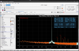
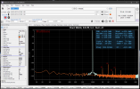
Captured the output using my Scarlett 4i4. The frequency spectrum (in Audition) of the right and left channels, both captured via the left front input Is posted below.

Screenshot 2023-11-20 at 12.28.45 PM.png
Screenshot 2023-11-20 at 12.28.32 PM.png
 

DonH56

Master Contributor
Technical Expert
Forum Donor
Joined
Mar 15, 2016
Messages
7,906
Likes
16,731
Location
Monument, CO
"Balanced" but the second harmonic dominates? Not differential, and/or maybe a bit of imbalance crept in? Or overdriving the capture device?

Still always cool to see DIY projects!
 

fpitas

Master Contributor
Forum Donor
Joined
Jul 7, 2022
Messages
9,885
Likes
14,212
Location
Northern Virginia, USA

wwenze

Major Contributor
Joined
May 22, 2018
Messages
1,329
Likes
1,881
Please use double-insulated cabling for your internal mains wiring. Especially when it's touching the low-voltage amp PCB. You generally don't want to DIY-twist the wires either, but I understand the desire to keep them together... which leads to the next point, those for-DIY wires are mains-rated, I hope?
 

Sokel

Master Contributor
Joined
Sep 8, 2021
Messages
6,127
Likes
6,204
Captured the output using my Scarlett 4i4. The frequency spectrum (in Audition) of the right and left channels, both captured via the left front input Is posted below.

View attachment 328107View attachment 328108
I would try REW or Multitone Analyzer for such measurements so I could see all the info.
Noise floor seems very high here (adding to the others posted above) ,what schematic did you used?
 
OP
IPunchCholla

IPunchCholla

Major Contributor
Forum Donor
Joined
Jan 15, 2022
Messages
1,116
Likes
1,400
"Balanced" but the second harmonic dominates? Not differential, and/or maybe a bit of imbalance crept in? Or overdriving the capture device?

Still always cool to see DIY projects!
I'm probably using the wrong term as I am just learning all of this. I'm using DRV134s which from IT's description are:
The DRV134 and DRV135 are differential output amplifiers that convert a single-ended input to a balanced output pair. These balanced audio drivers consist of high performance op amps with on-chip precision resistors. I'm guessing the second harmonic is partially tied to the capturing device, but also my circuit design and execution skills are probably the majority of it.
 

wwenze

Major Contributor
Joined
May 22, 2018
Messages
1,329
Likes
1,881
I would try REW or Multitone Analyzer for such measurements so I could see all the info.
Noise floor seems very high here (adding to the others posted above) ,what schematic did you used?
That's not noise floor, that's the FFT "floor" from not enough samples.
 

Sokel

Master Contributor
Joined
Sep 8, 2021
Messages
6,127
Likes
6,204
That's not noise floor, that's the FFT "floor" from not enough samples.
How so?
That's a measurement with the same window and half the FFT size:

FFT.PNG

and one with 4 times the measured one:

1700530788888.png

Differences would be big in noise If we would measure 20Hz for example but now at 1Khz are usually small.

(but I admit I'm unfamiliar with the program used,is just seem too high by the looks of it)
 
OP
IPunchCholla

IPunchCholla

Major Contributor
Forum Donor
Joined
Jan 15, 2022
Messages
1,116
Likes
1,400
How does one make a balanced line driver with a single opamp per channel and zero resistors? I'd like to see a schematic of that. Also, H2 at -75 dBr is inaudible but still lousy.
First is the schematic I based it on. The THAT1206 is pin compatible with the DRV134. The second is the schematic I used. -75 dBr is terrible. Given my knowledge and abilities I'm surprised it works at all.

Screenshot 2023-11-20 at 5.26.04 PM.png
Screenshot 2023-11-20 at 5.16.20 PM.png
 
OP
IPunchCholla

IPunchCholla

Major Contributor
Forum Donor
Joined
Jan 15, 2022
Messages
1,116
Likes
1,400
Please use double-insulated cabling for your internal mains wiring. Especially when it's touching the low-voltage amp PCB. You generally don't want to DIY-twist the wires either, but I understand the desire to keep them together... which leads to the next point, those for-DIY wires are mains-rated, I hope?
Thank you! I will switch it out for double insulated. Gauge wise they should be sufficient, but I doubt they are mains rated.
 
OP
IPunchCholla

IPunchCholla

Major Contributor
Forum Donor
Joined
Jan 15, 2022
Messages
1,116
Likes
1,400
How so?
That's a measurement with the same window and half the FFT size:

View attachment 328165

and one with 4 times the measured one:

View attachment 328166

Differences would be big in noise If we would measure 20Hz for example but now at 1Khz are usually small.

(but I admit I'm unfamiliar with the program used,is just seem too high by the looks of it)
It was Audition. FFT size was 66536. I don't know why I didn't just use REW. Pasted below. I haven't calibrated the interface yet.

Screenshot 2023-11-20 at 7.23.59 PM.png
 
OP
IPunchCholla

IPunchCholla

Major Contributor
Forum Donor
Joined
Jan 15, 2022
Messages
1,116
Likes
1,400
This is the measurement of the 2i2 by Amir. I had the gain much higher (just under clipping) as I was recording vocals previous to this and just left it. My setup was TRS in the Mic/Line input on the front.

index.php
index.php
 

DonH56

Master Contributor
Technical Expert
Forum Donor
Joined
Mar 15, 2016
Messages
7,906
Likes
16,731
Location
Monument, CO
You have a fairly large 60 Hz component that is likely either wire routing or a grounding issue. Probably an easy fix, once you find the coupling path. Might try moving the AC lines away from the boards for starters.
 

wwenze

Major Contributor
Joined
May 22, 2018
Messages
1,329
Likes
1,881
Well I'm late but FFT lesson anyway: What happened to result in the long flat horizontal line in the green plot is because the entire sampled duration does not contain just the pure tone, but also includes another type of sound. For example starting recording before starting playback, ending playback before ending recording, or even just knocking on the equipment.

For example in this plot the peak looks slim and neat
1700543573121.png


But watch what happens when I include the silence:

1700543627447.png


Familiar shape isn't it

Moral of story: Cut away the silence part or any non-periodic part. The mathematics of FFT is such that it only works on a periodic signal.
 

wwenze

Major Contributor
Joined
May 22, 2018
Messages
1,329
Likes
1,881
First is the schematic I based it on. The THAT1206 is pin compatible with the DRV134. The second is the schematic I used. -75 dBr is terrible. Given my knowledge and abilities I'm surprised it works at all.

Hold on, isn't THAT1206 a balanced INPUT to single-ended output, while DRV134 is a single-ended input to balanced output? How can they be pin-compatible? When their functionality isn't even the same
 

Sokel

Master Contributor
Joined
Sep 8, 2021
Messages
6,127
Likes
6,204
It was Audition. FFT size was 66536. I don't know why I didn't just use REW. Pasted below. I haven't calibrated the interface yet.

View attachment 328170
Here's the settings to get nice measurements in REW:

 
OP
IPunchCholla

IPunchCholla

Major Contributor
Forum Donor
Joined
Jan 15, 2022
Messages
1,116
Likes
1,400
You have a fairly large 60 Hz component that is likely either wire routing or a grounding issue. Probably an easy fix, once you find the coupling path. Might try moving the AC lines away from the boards for starters.
I know of one issue with the grounding that I need to fix (I cut a wire for routing reasons and forgot to reattach it. I’ll change out the AC wires and reroute them too. Thanks.
 
OP
IPunchCholla

IPunchCholla

Major Contributor
Forum Donor
Joined
Jan 15, 2022
Messages
1,116
Likes
1,400
Well I'm late but FFT lesson anyway: What happened to result in the long flat horizontal line in the green plot is because the entire sampled duration does not contain just the pure tone, but also includes another type of sound. For example starting recording before starting playback, ending playback before ending recording, or even just knocking on the equipment.

For example in this plot the peak looks slim and neat
View attachment 328192

But watch what happens when I include the silence:

View attachment 328193

Familiar shape isn't it

Moral of story: Cut away the silence part or any non-periodic part. The mathematics of FFT is such that it only works on a periodic signal.
Thank you for this info. That is super helpful.
 
Top Bottom