• WANTED: Happy members who like to discuss audio and other topics related to our interest. Desire to learn and share knowledge of science required. There are many reviews of audio hardware and expert members to help answer your questions. Click here to have your audio equipment measured for free!

Any Amp with I2S inputs?

You are still not telling us the necessary details about your goal/problem, so we can only guess, which is quite annoying and wastes our time and you may miss a much better solution.
What is the initial situation, where do you want to go, what is the source and which devices/speakers are involved?
i was just writing while you where :).

i apreciate your advice and knowledge.
when starting the thread i was really just aiming more for a overview of whats on the market and whats possible in regards of active crossovers.
while later i havent asked for to keep it focused on the thread title to not spread too much confusion.
 
some specs in a sketch
---------------------------------------------------------------------
-JAB5
Manufactorer Specs:
4x100W
THD 6ohm 5W 0.04%
SNR 97dB

TDA7498E

ADAU1701 (4 DACs: SNR of 104 dB, THD + N of −90 dB)

---------------------------------------------------------------------
WONDOM TAS5768
2x50W
THD 4ohm 1W 0.037%
SNR 103.6dB


---------------------------------------------------------------------
WONDOM TAS5756
2x30W
THD 0.05%
SNR 102dB


--------------------------------

alternative to these amps ,linux streamer, smls 100 pro feeding 2 DAC by I2S who then feed 2 propper class D amps.
more setup work but better components can be used.
 
Last edited:
Hey,

I am also looking for Digital amps taking I2S as inputs and which can deliver 15-20W outputs for my speakers satellites.
My requirements are slightly different as I am receiving the Audio signal via an I2S stream - see DIY WiSA Home-theater and I am looking for board with minimal footprints in order to integrate them (Receiver+Amps) in small satellite speakers - something like: https://www.instructables.com/P-CUBE-Speaker-System/.

I have found these projects that fits my needs:
- https://github.com/tonyp7/TAS5806M-Audio-Amplifier
- https://github.com/Darmur/bassowl-hat
- https://hackaday.io/project/175727-tas5825m-i2s-audio-amp

However, it seems that to take benefits of the integrated DSP of these chips, special software (Purepath console / PPC3 from T.I) and evaluation boards are needed (costly...)
yes, the restrictions on purepath are a bummer.
the jab5 is easier to handle in this regard with its ADAU, which you allready have (?)
sorry no big help here.
 
Well, if such amps exist, it would be an easy cool way to have multichannel (out of the gpio pins of a rpi5 for instance) without the need for a multichannel DAC.
actually, this thread got me interested, i didn't know amps with i2s inputs was a thing but Analog Devices seems to have a whole family of them up to 30W. I didn't read thoroughly but seems that they don't need MCLK, accept up to 96kHz, and you can even have one that receives the i2s signal operating in mono and passing the unused channel to the next one. They also require very few parts. A bunch of these and a RP5 could make a very cool tiny diy HT system or active speaker with software crossover. neat!


example: SSM3582:
1728577793797.png
 
example: SSM3582:
1728577793797.png
Note that these amps do not have digital PWM modulators:

IMG_9215.jpeg

They contain DACs to convert to analog first, and then apply analog PWM modulation.

Not all I2S input Class D amp chips are like this though. Some directly generate PWM digitally.
 
Note that these amps do not have digital PWM modulators:

View attachment 397841
They contain DACs to convert to analog first, and then apply analog PWM modulation.

Not all I2S input Class D amp chips are like this though. Some directly generate PWM digitally.
How they work inside I personally don't care about, the advantage I see is having several channels synced without additional hardware other the RPI and the amps
 
How they work inside I personally don't care about, the advantage I see is having several channels synced without additional hardware other the RPI and the amps
That's okay. Others still might. :) Especially given that the words "full digital amp" are thrown around very quickly, which these are clearly not. It's not a value judgment either way, though. It's just an observation to be aware of.
 
Thank you Voodooless for your clarification, I indeed believe it was fully digital until I look more in detail.
Here is the latest (I think) product of Texas Instrument - TAS5828M which is capable of 2*50W output:

Texas Instrument TAS5828M
1728608639565.png


I think I will go down this path for my project but everything need to be built... Not much in the Open Source community !
 
Hello,

I have received the draft design, from a hired free-lance, to use TAS5828M and I would like to get your opinion before sending it for manufacturing:

1729040759001.png

Top Layer.png
Bottom Layer.png
Top 3D.png


Looking forward for your feedback,
 
Spdif can achieve 0.00018% THD+N with just 24 bit 48kHz. Going 192kHz is due to believing marketing gimmicks.
 

Attachments

  • CS43131.png
    CS43131.png
    138.4 KB · Views: 26
its very minimalistic but somehow quite nice, no need for an DAC nor DC blocking caps, not sure how it compares to other solutions, but its neat.
Looks like x5r or 7 are used on the output filter, maybe go for COG there, even its not directly in the signal path.
 
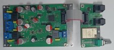
I have an amplifier with an I2S input, an amplifier that is essentially a power PWM DAC.
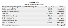
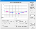
PDAC+Input ESP32.jpgPDAC-100.pngSummary.pngLevel Sweep 4R 32V Ch0 Ch1.png

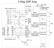
It was designed for an active three-way speaker system and contains on the board a DSP ADAU1452 and three power 100W PWM DACs with feedback on the PWM signal, which achieves lower nonlinear distortions than similar solutions without feedback.
ADAU1452 has a good ASRC, which eliminates the need to synchronize the clock frequencies of the signal between the itsonic and the receiver.

You can read more about it here.
https://www.diyaudio.com/community/threads/3-way-dsp-amp.415065/#post-7734938
 
its very minimalistic but somehow quite nice, no need for an DAC nor DC blocking caps, not sure how it compares to other solutions, but its neat.
Looks like x5r or 7 are used on the output filter, maybe go for COG there, even its not directly in the signal path.
Sorry @cobby , I just noticed your answer.

Would you be able to give me a bit more detail on what you mean ?

I am preparing to place the order for manufacturing and I believe almost all capacitors were switched to Ceramic as you advised by JLPCB:
1732941950489.png
 
What output power do you expect to get from this amplifier?

What level of nonlinear distortion is acceptable to you?

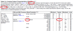
As per datasheet, TAS5828M should be able to output 50W stereo (100W mono) with a distortation around THD+N ≤ 0.03% at 1 W, 1 kHz.
I am not really sure what it means but it seems quite good for this kind of chip !
TAS5828M datasheet
 
I am not really sure what it means but it seems quite good for this kind of chip !
If you want to get distortion at the level of 0.03% per 1W, then you definitely need to use a different low-pass filter at the output of this chip.

By the way, I doubt that the chokes you installed will really withstand a current of 5A with an inductance loss of 10%.

If you want to get as little nonlinear distortion at the amplifier output as possible, then read this document, everything is well described and shown in it. Figure 29 shows the dependence of amplifier distortion with different types of output chokes. And below it is written what type of capacitors it is desirable to use at the amplifier output.
 

Attachments

  • slaa701a.pdf
    1.5 MB · Views: 8
If you want to get distortion at the level of 0.03% per 1W, then you definitely need to use a different low-pass filter at the output of this chip.

By the way, I doubt that the chokes you installed will really withstand a current of 5A with an inductance loss of 10%.

If you want to get as little nonlinear distortion at the amplifier output as possible, then read this document, everything is well described and shown in it. Figure 29 shows the dependence of amplifier distortion with different types of output chokes. And below it is written what type of capacitors it is desirable to use at the amplifier output.
Thank you for the inputs !

After checking your document as well as the TAS5828M Evaluation board, I believe I can change the inductance to Wurth Electronik - 74435 or 74436 family - with specs in range of
7 μH -10 μH in the LC filter, a capacitor value of 0.68 μF - 0.47 μF - rated for 35V-50V see Chapter 5.5.
The evaluation board is using 7447709100 - Inductor, Shielded Drum Core, Ferrite, 10uH, 7.1 A, 0.01294 ohm, SMD
 
Back
Top Bottom