• WANTED: Happy members who like to discuss audio and other topics related to our interest. Desire to learn and share knowledge of science required. There are many reviews of audio hardware and expert members to help answer your questions. Click here to have your audio equipment measured for free!

DIY WiSA Home Theater system

Glider95

Member
Joined
Aug 18, 2024
Messages
23
Likes
40
Hello guys,

I am diving into the audio world as I would be interested to add a Surround/ Dolby Atmos to my living room.

I am trying to avoid wires and thus look into what could be done DIY & Wireless. Unfortunately, it seems that there is not many reliable protocols that are able to achieve bandwith & latency requirements of high quality audio.

Dolby Atmos FlexConnect -> Almost brand new, not much info.

Bluetooth -> Quickly read that it will not achieve latency requirements ?

RadioFrequency -> Have not look into that.

And finally, there is WiSA that is a proprietary protocol using 5.2-5.8Ghz frequency - One person seems to recently look into retro-engineer this protocol so it can be used for DIY, but not much news: Build a WISA receiver.
After researching a bit everywhere, I might have found a way to buy the WiSA transmitter and receivers without buying in bulk. I will not post the link yet as I would prefer to try first and update you later (but if you are really interested, please contact me in private message.)

In term of hardware, the idea would be:

INPUT & TX:
- A 2nd hand WiSA SoundSend that has the advantage to be Dolby certified OR from an eArc HDMI Audio extractor with I2S output to the WiSA transmitter.
(I also saw the Orange Pi5 has en eArc HDMI but I did not find any active project on that + the Dolby stuff would still be problematic if I understood correctly?)
- Transmit using a WiSA TX board.

RX:
- a WiSA RX board has I2S & I2C outputs and thus could be use to a mini amp / DSP ? This is where I need your expertise !
HDMI Extractor ---I2S---->TX --Wireless--> RX --- I2S---> Amp/DSP? ---> Speakers.

Pin out is just for schematics

proposition.png


One of my concern is how usable is the RX I2S output as it could be encrypted. After long research, I do not believe it is (see schema of a WiSA DAC and a WiSA ready Amp that used to be sold) but only real test will tell.
WiSA DAC: WiSA Amp:
WiSA DAC.png
1723977947781.png


Looking forward for your feedback,
 
Have you considered AES67/Dante?

Combined with PoE, you could have just a single Ethernet cable going to each speaker, which carries both power and data.

Genelec make speakers like that, but not sure if it's viable as a DIY project.

Fwiw, I'd much rather troubleshoot a wired data connection than a wireless one.
 
I have not look into AES67/Date as:
- Power outlet is not really an issue in my setup but running other type of cable is not possible.
- A possible evolution of the project could be real wireless (i.e: on battery+solar power - no power wire) for the satellites/surrounds that will be added just for movie nights.
 
Genelec make speakers like that, but not sure if it's viable as a DIY project.
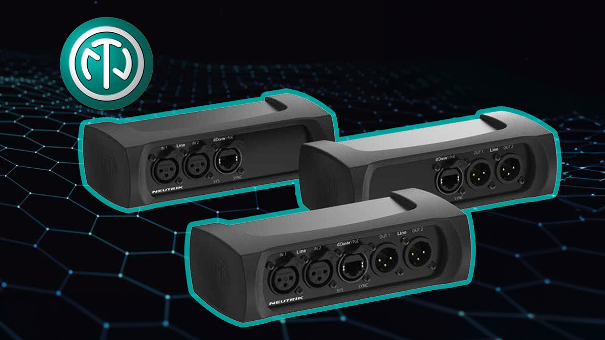
There are Dante i/o devices that can accomplish this:
 
Bluetooth -> Quickly read that it will not achieve latency requirements ?
Auracast / LE Audio is designed to cover surround, among other use cases. I haven't looked for open implementations - they may not be there yet.
(I also saw the Orange Pi5 has en eArc HDMI but I did not find any active project on that + the Dolby stuff would still be problematic if I understood correctly?)
A couple of the Khadas VIM models too. Multichannel seems possible but poorly documented. See https://www.audiosciencereview.com/...-know-about-hdmi-earc-here.55559/post-2030240
 
+ the Dolby stuff would still be problematic if I understood correctly?
You will need a surround decoder. An AVR is the most common solution and usually the most economical. Or on a computer you can use DVD/Blu-Ray player software, and a multichannel soundcard. I don't know what software supports Atmos. VLC Player is free and it supports DVD and Dolby Surround, but the last time I checked, Blu-Ray was not fully supported.
 
Auracast / LE Audio is designed to cover surround, among other use cases. I haven't looked for open implementations - they may not be there yet.

A couple of the Khadas VIM models too. Multichannel seems possible but poorly documented. See https://www.audiosciencereview.com/...-know-about-hdmi-earc-here.55559/post-2030240

Thanks for the links, I will look into them !
Khadas VIM looks interesting but it is not super cheap and would still have the issue of the Dolby proprietary decoding.

You will need a surround decoder. An AVR is the most common solution and usually the most economical. Or on a computer you can use DVD/Blu-Ray player software, and a multichannel soundcard. I don't know what software supports Atmos. VLC Player is free and it supports DVD and Dolby Surround, but the last time I checked, Blu-Ray was not fully supported.
Understood !
Therefore, the idea of a 2nd hand WiSA SoundSend will make it easier as everything is already handled until transmission.

Next steps for me:
- To find a 2nd hand SoundSend.
- I found 2 Klipsch R34C boards (with amps and WiSA receiver) so it should allow me to check if RX can be swapped with other boards (not S/N locked or something like that) for cheap (20e each and can re-use the power supply and amps for my DIY speakers)
- Order new TX and RX (To also check if TX can be swapped)
- and with all these things, check if I2S is usable as it is to integrate to other devices.

Capture.JPG
 
Hello,

I start to receive some of the parts.
Here is a zoom-in of the receiver part
32e87ae3-2f3c-4896-9b7e-77b9dc93c6b7.jpeg


I will add more photos of the receiver including the connection with the Klipsch Amp and also the emitter part (Wisa SoundSend) in a few days when I am back home!
 
Hello,

I start to receive some of the parts.
Here is a zoom-in of the receiver part
View attachment 390067

I will add more photos of the receiver including the connection with the Klipsch Amp and also the emitter part (Wisa SoundSend) in a few days when I am back home!
I wish one day can design a PCB like that, with all those antennas and their stitching vias.... :D

@Glider95 good luck, I will be following
 
Here is some updates !

I have received one WiSA receiver + DSP + Amp coming from a Klipsch RW34-C:
thumbnail_IMG_6123.jpg

Receiver front:
We can see the main Summit Wireless chip, under the shield it is a Airoha AL7230 - 2.4-5ghz Wireless A/B/G
thumbnail_IMG_6109.jpg

thumbnail_IMG_6110.jpg


DSP "zeno_speaker_DSP_V.C" front based on ADAU1701:
The DSP from Klipsch is based on ADAU1701 and looking at the traces, I don't think there is any kind of encrypting/decrypting on this board.

thumbnail_IMG_6111.jpg

thumbnail_IMG_6112.jpg


Amp front:
thumbnail_IMG_6113.jpg
IMG_6114.jpg


And I also receiver a WiSA SoundSend !

Transmitter front:
thumbnail_IMG_6118.jpg
thumbnail_IMG_6121.jpg


and the main board:

thumbnail_IMG_6120.jpg
thumbnail_IMG_6119.jpg


My next test is to find how to power up the RX without the original power supply and see if it can be detected on the WiSA App.
In parallel, I have exactly the same components coming with a power supply included in few days.
 
Last edited:
Still waiting for the other Receiver with the power supply:

Here is the mapping that I could figure out with continuity testing:

There is Vin 3.3V , I still have to figure out Green and Pink Vin (maybe 1.2V)
I think I have found the I2S from RX to ADAU.
And there is 2 lines (Light blue and pink) from RX to LPC11E67 (connected via band wire) which I think is used to control the LED at the back of Klipsch speaker (to set the speaker position) and put the RX in pairing mode.
-> Right now I am not able to pair the receiver with the Emitter because I don't how which pin is used for that -> Should be resolved with the next unit coming as it includes the reset button.
There is 3 unknown pin (Orange, blue, green).
On the RX, there is a small NAND memory MXIC MX 25L8006E maybe retaining the speaker pairing, name etc... -> Is it readable?

All ideas or comment are welcomed !

1725875602756.png
 
Some updates:
The wiring schema above have some errors in term of input voltage, need to correct.

However, I have succesfully:
- Paired both receivers with the SoundSend (unfortunately one DSP board seems to be dead but both receivers appear with different MAC addresses when using the working DSP)
- Transmitted Dolby Digital audio coming from Arc HDMI and Optical to speaker plug to the Amp board
- Switched the speaker to different channels (Sub, Center, Surrounds) with audible differences on the speaker output
- Played with the EQ provided in the app with audible difference.
- Changed volume on the app and from the TV remote (via Arc) and being reflected on the emitter and the app.
Update:
- I believe I managed to read the I2S signal coming from RX using an ESP32 and serial port.

Code:
#include <driver/i2s.h>
// I2S microphone configuration
#define SAMPLE_BUFFER_SIZE 512
#define SAMPLE_RATE 8000
#define I2S_MIC_CHANNEL I2S_CHANNEL_FMT_ONLY_LEFT
#define I2S_MIC_SERIAL_CLOCK GPIO_NUM_26
#define I2S_MIC_LEFT_RIGHT_CLOCK GPIO_NUM_25
#define I2S_MIC_SERIAL_DATA GPIO_NUM_22
// I2S config
i2s_config_t i2s_config = {
    .mode = (i2s_mode_t)(I2S_MODE_MASTER | I2S_MODE_RX),
    .sample_rate = SAMPLE_RATE,
    .bits_per_sample = I2S_BITS_PER_SAMPLE_32BIT,
    .channel_format = I2S_CHANNEL_FMT_ONLY_LEFT,
    .communication_format = I2S_COMM_FORMAT_I2S,
    .intr_alloc_flags = ESP_INTR_FLAG_LEVEL1,
    .dma_buf_count = 4,
    .dma_buf_len = 1024,
    .use_apll = false,
    .tx_desc_auto_clear = false,
    .fixed_mclk = 0};
// I2S pin config
i2s_pin_config_t i2s_mic_pins = {
    .bck_io_num = I2S_MIC_SERIAL_CLOCK,
    .ws_io_num = I2S_MIC_LEFT_RIGHT_CLOCK,
    .data_out_num = I2S_PIN_NO_CHANGE,
    .data_in_num = I2S_MIC_SERIAL_DATA};
int32_t raw_samples[SAMPLE_BUFFER_SIZE];
void setup() {
  // Initialize serial output for plotting
  Serial.begin(115200);
 
  // Setup I2S
  i2s_driver_install(I2S_NUM_0, &i2s_config, 0, NULL);
  i2s_set_pin(I2S_NUM_0, &i2s_mic_pins);
}
void loop() {
  size_t bytes_read = 0;
 
  // Read I2S data
  i2s_read(I2S_NUM_0, raw_samples, sizeof(int32_t) * SAMPLE_BUFFER_SIZE, &bytes_read, portMAX_DELAY);
  int samples_read = bytes_read / sizeof(int32_t);
  // Initialize range to stabilize the serial plotter display
  int rangelimit = 3000;
  Serial.print(rangelimit * -1);
  Serial.print(" ");
  Serial.println(rangelimit);
  // Compute and plot the average value of the samples
  float mean = 0;
  for (int i = 0; i < samples_read; i++) {
    mean += raw_samples[i];
  }
  mean /= samples_read;
  // Print mean to Serial Plotter
  Serial.println(mean);
}


1726142888327.png

Next steps:

- Try to extract ADAU1701 firmware-> To be able to re-use this configuration in other ADAU1701 board.
- Try to extract LPC11E67 firmware -> To be able to re-use the configuration ?
- Figure out the whole In/Out of the 24 pins of the RX board...
- Is it needed to figure out the I2S Signal ? Is one individual channel sent to each RX ? Or is it multiplexed (12 channel?) and then the DSP on the receiver part select which channel to read?

Any inputs are welcomed as I am sure that I am missing some stuff.
 

Attachments

  • 1726141732105.png
    1726141732105.png
    84.4 KB · Views: 31
Last edited:
Love your project and i wish i could contribute a bit, but unfortunately this is above my pay grade. I have more questions than answers.
When i read your previous posts, i was also wondering what is the signal flow:
- Do all receivers receive all channels and then somehow select one that they send to the ADAU1701 that outputs different signals for, say, tweeter, woofer, etc of the speaker playing that channel?
- Do each receiver receive only the channel they need, and send it to the ADAU1701?
- yet another possibility?
The first case would be ideal but In either case, if the i2s signal is decoded (that is the best news of all this) and you are capable of taping it, i would say you can do what you want with it. As i understand it (very little i need to say), that signal should be agnostic about who receives it.
I understand your desire to reverse engineer the firmware of the microcontroller, but if not feasible, you can always steal the i2s signal and use the two boards as if it was one device. I would forget about the ADAU as it is probably programmed specifically for the original speaker (? just wondering).
Regarding the i2s signal, it should be easy to know if it is a two channel per line signal or a multiplexed one, just checking the frequency of the clocks and the data lines.
I see in your diagram you only identified 2 i2s data lines (SDATA IN 0 and 1), do you think there might be more? because otherwise they are either multiplexed -strange, because in this case one data line would be enough - or there are only 4 channels per board.
 
Don't worry, I have even less knowledge than you have, I am just tinkering around and I have no basic knowledge of Audio !

- Do all receivers receive all channels and then somehow select one that they send to the ADAU1701 that outputs different signals for, say, tweeter, woofer, etc of the speaker playing that channel?
- Do each receiver receive only the channel they need, and send it to the ADAU1701?

If it was Option 2, wouldn't it means that the TX would emit on 8+ different frequencies within the 5.2-5.8Ghz band (with risk of overlapping with house wifi,etc..) ?
Eventually, if I could spy on this network that is within the WiFi spectrum, I guess we could figure it out.

The first case would be ideal but In either case, if the i2s signal is decoded (that is the best news of all this) and you are capable of taping it, i would say you can do what you want with it. As i understand it (very little i need to say), that signal should be agnostic about who receives it.
I have tried to read the captured data from the screenshot above but the Arduino IDE is not able to save a file locally on the computer, I would need an SD Card reader to connect to my ESP32, it seems.
But if I can do that, I should be able to confirm if I am looking at single channel (or more) on the I2S Data pin that I am reading.

Regarding the i2s signal, it should be easy to know if it is a two channel per line signal or a multiplexed one, just checking the frequency of the clocks and the data lines.
Any idea how I could try to do that ? As far as I understand, when I2S signal is multiplexed, it is using a TDM (Time Division Multiplexed) which can only carry 4 channels.

I see in your diagram you only identified 2 i2s data lines (SDATA IN 0 and 1), do you think there might be more? because otherwise they are either multiplexed -strange, because in this case one data line would be enough - or there are only 4 channels per board.
It is highly possible that there is more data lines, I just assumed this looking at the tracks visible on the PCB. Looking at the document below, it seems that there is indeed 2 Data lines ?

Here is a DAC that Summit Wireless used to sell which shows that there is only 3 Lines level:

1726168017273.png


I just remembered that I had an Amplifier board reference design from the files I found online:
1726168511390.png
 
Any idea how I could try to do that ?
If each data line carries only two channels (regular i2s). With an oscilloscope, measure:
LRCLK frequency = sample rate
BCLK frequency = sample rate * 2 * 32 typically

If it is a multichannel TDM signal, BCLK frequency will be much higher to accommodate the several channels.
I will be surprised if in these boards each data line carries more than two channels, what for? The board is intended for a single speaker.
 
I do not have an oscilloscope but maybe I can try to figure something out with some electronics !

However, wouldn’t the last picture I added confirm that there is only 2 data lines (SD0 and SD1) which then with 2 TDM -> 8 channels ?
 
Last edited:
I do not have an oscilloscope but maybe I can try to figure something out with some electronics !

However, wouldn’t the last picture I added confirm that there is only 2 data lines (SD0 and SD1) ?
No, there are two possibilities:
1. Regular i2s: each data line carries two channels. If there are two data lines (SD1 and SD0), there are a total of 4 channels possible. Could well be that not all 4 are used and some of them are just zeros.
2. multichannel TDM: one single data line carries several channels, like for instance 8 channels. I have never seen multichannel TDM using more than one data line, but maybe it is possible.
 
Can this project be simplified using the Bang & Olufsen product off the shelf? I wonder if it is compatible with any WiSA transmitter?
1726175513775.png
 
Can this project be simplified using the Bang & Olufsen product off the shelf? I wonder if it is compatible with any WiSA transmitter?
View attachment 391953

I think it is actually really similar components inside, except that B&O sell this for 200USD while I can get the WiSA receiver PCB for 20 USD !
It should be compatible with the WiSA SoundSend (like my Klipsch salvage parts are compatible with it). I will try the B&O app on my setup and see.

Another interesting explanation found on B&O Website:

1726206005902.png
 
Last edited:
Back
Top Bottom