antcollinet
Grand Contributor
Was the question you asked directly to 3eaudio? Have you dm'd them here @3eaudio ?Ok. Excuse me.

Was the question you asked directly to 3eaudio? Have you dm'd them here @3eaudio ?Ok. Excuse me.
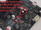
Hi! I wrote to the seller in the official 3Eaudio store. The seller sent a "recommendation from engineers" - to replace 2 capacitors. (look pics.1)Was the question you asked directly to 3eaudio? Have you dm'd them here @3eaudio ?
You can't measure them while they are in circuit - everything else connected to the circuit will influence the measurement.Hi! I wrote to the seller in the official 3Eaudio store. The seller sent a "recommendation from engineers" - to replace 2 capacitors. (look pics.1)
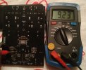
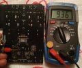
Before replacing these capacitors, I checked them on both boards. (look pics.2,3)
All 4 capacitors are serviceable. They have a capacity of 9.10mF - 9.90mF. It doesn't make sense to change them.
Here the advice was not just to change the capacitors. They are in good condition. But their capacity needs to be changed. The default capacity on the board is 10 uF. 3E advises replacing the capacitors with 1 uF capacity where the pop is. I have a similar problem when turning off on one channel on my stereo board. 3E gave me the same advice.The purpose of the replacement is to reduce the capacity.You can't measure them while they are in circuit - everything else connected to the circuit will influence the measurement.
What is the value shown on the capacitor body? (It's uF BTW, not mF).
We do not listen to sine sweeps or white noise.
Say that you're completely maxing out this Amp, playing well mastered music with even spectral distribution:
View attachment 333107
With 165W Peaks at <500Hz, you will only output ~8W at 5kHz, ~4W at 10kHz, and ~0.4W at 20kHz.
View attachment 333110
In this way, Amir's THD+N vs Power vs Frequency graphs can be a bit misleading.
100+ Watts at 5/10/20kHz is absolutely insane and does not represent real world usage.
A solution is to instantly disconnect the speaker connection immediately after the AC power line is turned off, or reset the TPA3255 and stop the amplifier from running.
This is very difficult. There is a simpler method (2), with one relay. In this case, the acoustic systems do not need to be disconnected.I put a relais in the + of the speaker and another switch. First amp on an then relais on, then relais off and amp of.
Have you actually tried this method and confirmed that it eliminates the popping noise?Н! How to get rid of the clicking sound in the speaker system when the module is turned off. There are two methods.
First.
You do not need to turn off the primary alternating voltage going to the power supply. This is exactly when this clicking sound occurs. This is due to the attenuation of the constant voltage, which is incorrectly perceived by the module circuit ...
You need to turn off the secondary constant voltage going from the power supply to the module. There should be no clicks.
Try it. If it does not help, I will tell you about the second method. The circuit is very simple. But you will need to use one simple relay, with one contact.
There is no mention of "PS_CTRL" in the data sheet for TI's TPA3255. There is no such pin in the pinout of the IC chip.Checked. Unfortunately, this method does not work. The capacitors on the module itself are discharged. After 0.5 sec - a click (pop noise).
Then the second method. It will work, because this is a function of the module itself.
There is a comb with contacts on the module.
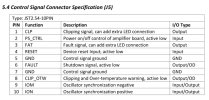
If you close the contacts PS_CTRL and GND (there are two of them on the comb), the board will turn off. Open - it will turn on. The shutdown is instantaneous, without clicks (pop noise).
This way you can install a switch, and use it to turn the module on and off. It is better to close and open through a 50 Ohm resistor, but not necessary.
The downside of this method is that the power supply is always under voltage.
But you can improve it and turn off the primary voltage. After the switch, you need to install a 220 volt relay. And connect its normally closed contact between PS_CTRL and GND. Then, after applying 220 volts, PS_CTRL and GND will open, and the amplifier will turn on. And when removing 220 volts, PS_CTRL and GND will instantly close, and the amplifier will turn off without a click (pop noise).
The relay can be like this HJQ-13F-220VAC-1Z
There is no mention of "PS_CTRL" in the data sheet for TI's TPA3255. There is no such pin in the pinout of the IC chip.
I think "PS_CTRL" is probably an input created in the 3e audio amplifier circuit. Does it actually go into a sleep-like state?
It is important to know the function of "PS_CTRL". I have looked at the table in the 3e audio manual many times, but there is no detailed explanation.What does the technical data sheet of TPA3255 have to do with this?
We are talking about the 3E Audio module here. He has his own data sheet. See the screenshot.
Take a jumper and try it yourself. It works flawlessly, as I wrote above:
- If you close the contacts PS_CTRL and GND (there are two of them on the comb), the board will turn off. Open - it will turn on. The shutdown is instantaneous, without clicks (pop noise).