OP
- Thread Starter
- #201
Paul, if you take the simplest case, F1+F2 and a pure H2 distortion, and F1 and F2 are close to Fs/2, as in our case (19kHz, 20 kHz and Fs/2=24kHz), then we get only one distortion component, F2-F1 = 1kHz below Fs/2. Everything above Fs/2 is prohibited by Nyquist theorem, which says that input signal can be properly reconstructed from its samples if the signal frequency is <Fs/2. So the components 2F1, 2F2 that all lie above Fs/2 and are H2 product are prohibited and are normally removed by a brickwall filter tuned just below Fs/2. This is for H2.
H3 creates equally spaced skirts around F1 and F2 at 2F1-F2 and 2F2-F1 frequencies, i.e. at 18kHz and 21kHz. These products are OK. So the lines of even harmonic distortion we can see at the left side as multiples of 2 x (F2-F1), 2kHz as a product of H2, 3kHz of H4 etc. Same for skirts that are created by odd harmonic distortion components. But, we have set H2 to -60dB approx and H3 to -80dB approx, all else H4 etc. below -200dB, so we have only H2 and H3 distortion. We may see thus only the F2-F1 (1kHz) at -60dB and 2F1-F2 and 2F2-F1, i.e. 18 and 21kHz skirts at -80dB. There must be no 8-12kHz lines in the 16dB signal which has a noise bottom at about -132dB. Those lines would be somewhere at -200dB, thus invisible in this plot. This is very basic information and we who work with analog circuits know and are able to identify distortion components immediately. Your 8-12kHz lines are a product of calculation only.
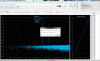
Attached is a measured CCIF distortion of a tube amplifier with similar H2 and H3 as described above, plus a small H4. Attached is also a Burr Brown paper on IMD.
View attachment 45146
With ADC sampling 96kHz we may look to 48kHz but not higher.
http://www.ittc.ku.edu/~jstiles/622/handouts/Two-Tone Intermodulation.pdf
That's correct for an ADC. But DISTORT is simulating a DAC with the non-linear distortion being applied after the samples are converted, in effect, in the analog domain, with no post-filter, unless you select one in the settings.
Just searching around, here's a real world example posted here, on ASR, of measured IMD at the output of a DAC:
Look similar?
Last edited:
") I shared an example previously by someone else. This time, I just used my own DAC/ADC capture, with two filters in the path:
I shared an example previously by someone else. This time, I just used my own DAC/ADC capture, with two filters in the path: