• WANTED: Happy members who like to discuss audio and other topics related to our interest. Desire to learn and share knowledge of science required. There are many reviews of audio hardware and expert members to help answer your questions. Click here to have your audio equipment measured for free!

Beta Test: Multitone Loopback Analyzer software

OP
pkane

pkane

Master Contributor
Forum Donor
Joined
Aug 18, 2017
Messages
5,732
Likes
10,413
Location
North-East
Lets follow a thought.
We take a music sample from a song of a band consisting of 3 instruments and a singer.
At any given time this song will have 4 tones along with their harmonics,their anharmonics (I don't know if that's included in electronics,I know it from music),etc.
So we get an 1 sec sample and sim it,can't we?
Will that be representative?

Now that you've mastered MT, you should start looking into DeltaWave ;) No need to simulate music, just use any music you want as a test tone.
 

Sokel

Master Contributor
Joined
Sep 8, 2021
Messages
6,207
Likes
6,321
How about just a randomized level multitone? You can do this one already:

View attachment 224142
Yep,that looks like it.
random.PNG
 
OP
pkane

pkane

Master Contributor
Forum Donor
Joined
Aug 18, 2017
Messages
5,732
Likes
10,413
Location
North-East
Could you add a "Cool-down" option too? Just a selectable seconds counter like the "Warm-up", but after the test tone and without the sound?

It would be very usable when doing long sweeps with a lot of power to prevent smoking the dummy load with powerful amplifiers. It would also keep the temperature of the dummy load constant to make more comparable results during the run even not using the extreme power.


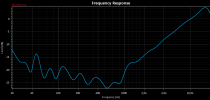
We talked about the crosstalk measurements before (About the possibility to add a dBr option for the frequency response graph too and using for example the left output and right input to measure multitone signals) and I PhotoShopped a settings page for it:

index.php


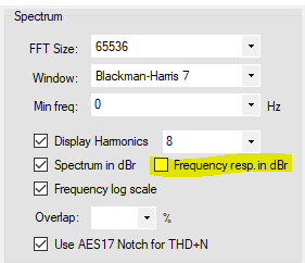
Could you implement it?

Thanks for the suggestions. Cooldown is a good idea, I’ll definitely add it.

The frequency response behavior changed a while back based on your request to try to move the graph to 0dBFS line by default. Is this not working?
 

Sokel

Master Contributor
Joined
Sep 8, 2021
Messages
6,207
Likes
6,321
And I’ll expect a long list of DW bug reports from you by later today ;)
Not today,I'll go to the beach in a while and I will leave when the sun go down! :cool:
But I'll find ways to break it,don't worry :facepalm:
 

Rantapossu

Addicted to Fun and Learning
Joined
Jul 21, 2022
Messages
528
Likes
375
Thanks for the suggestions. Cooldown is a good idea, I’ll definitely add it.

The frequency response behavior changed a while back based on your request to try to move the graph to 0dBFS line by default. Is this not working?

Thanks!

Maybe I'm too dummy to use it or I have misunderstood the situation or the terms. Maybe both ;)

I'll try to explain:

1. I use the left output and the right input and choose for example 32 tone multitone signal
2. After the measurement the lowest point is for example at -15 dBFS and highest point of the curve is at 0 dBFS at the frequency curve. The line is moved that the highest peak is at 0 dBFS. It won't be the almost straight line like it would be if I used the left output and left input like normally measuring the frequency response and not the crosstalk.
3. I expect that when measuring crossfeed (L->R), the line should be somewhere like -85dBFS and -100 dBFS depending on the card and cables and not at the 0 dBFS line.
4. I thought that disabling the dBR would drop the line to the -85 dBFS to -100 dBFS region. Have I misunderstood it?
 

Rantapossu

Addicted to Fun and Learning
Joined
Jul 21, 2022
Messages
528
Likes
375
L -> R measurement now:

1660484552485.png


I'd expect the top of the line to be like -80 dB and the bottom at -105 dB or something like that. Would disabling the dBR drop the line there?

To compare, at the spectrum display when the dBR setting is ticked "off", the sine signal (with -30 dB gain), is at -30 dB at the graph (with the unity gain) and when the setting is "on", the -30 dB signal is at 0 dB like it should be. Should it be the same here, if there were a selector for the dBR? When disabling the dBR I would see the truth about crosstalk?
 

Attachments

  • 1660484531170.png
    1660484531170.png
    25.2 KB · Views: 31
OP
pkane

pkane

Master Contributor
Forum Donor
Joined
Aug 18, 2017
Messages
5,732
Likes
10,413
Location
North-East
Yes, I thought of that, but a sawtooth isn't one of the stock choices in MT. Maybe that is a worthy feature request that it have a sawtooth test option. Probably easier to add than filtered multi-tones.

Sawtooth will be in the next update:

1660489101794.png


1660489143358.png
 
OP
pkane

pkane

Master Contributor
Forum Donor
Joined
Aug 18, 2017
Messages
5,732
Likes
10,413
Location
North-East
Wanted to ask your help to test MT output to a multi-channel device. This should work with WASAPI and possibly ASIO drivers, outputting to channels other than just left and right. This version (1.0.39) also implements the sawtooth test signal, but I'm not ready to call it a new release yet:

https://app.box.com/s/qbrh3czrvudclkqs9n8lm806k3hzmjx5

For now, you can't output to more than two channels at a time (I can add that, if that's of value). When MT detects a multi-channel device, the channel selector will list the additional channels, like this:

1660519632547.png


L and R channels are the same as channels 1 and 2, so selecting 1 is the same as L. You can also select 1+2 to select output to L+R channels, or 3+4, or 2+7, or any combination of two channels, or any single channel for output.

For now, input is still only on L or R channels.

Let me know how this works and especially if it doesn't. If you use WASAPI, test higher number channels with and without Exclusive mode, as well as left and right.

I'll test this more myself once I can locate my 5.1 channel Soundblaster DAC :)
 

MC_RME

Addicted to Fun and Learning
Technical Expert
Audio Company
Joined
May 15, 2019
Messages
880
Likes
3,630
Simply set your Pro into Multichannel mode and loopback all I/Os via cable.
 

Blumlein 88

Grand Contributor
Forum Donor
Joined
Feb 23, 2016
Messages
20,846
Likes
37,794
If I use triangle and set it for 0 db output, and adjust the multi-tone setting to 44,100 hz in the panel I get a good result.
1660527285432.png


In sawtooth with the same settings it clips badly until I turn down the output gain, and I get this.
1660527476469.png


If I limit it to 20,000 hz it works okay.

1660527592514.png


It only takes a reduction of a couple db to get it looking okay.
1660527770644.png
 

Blumlein 88

Grand Contributor
Forum Donor
Joined
Feb 23, 2016
Messages
20,846
Likes
37,794
This is different from the previous example in that everything is running at 44 khz rather than 88.
I get clipping with the upper limit set to as low as 15 khz. If I drop the upper limit to 14 khz or less it is okay.

1660528263997.png


It shows clipping at 14 khz, but actually just misses being clipped by .09 db.

1660528376925.png


I tried setting the input device at a higher sample rate and get the same result. So it appears the sawtooth signal generated is clipping the output device if the upper limit is too high.
 

Blumlein 88

Grand Contributor
Forum Donor
Joined
Feb 23, 2016
Messages
20,846
Likes
37,794
In this example output device is at 44 khz and input device is at 88 khz. If I set the frequency to a lower value, 20 hz in this case, then the upper limit must be lowered to prevent clipping.

1660528984223.png


Even here an output gain reduction of only -2db gets it just under clipping all the way to 20 khz. Sorry my sawtooth request is causing trouble. But it is a handy signal to have for some purposes.
1660529182688.png
 

Blumlein 88

Grand Contributor
Forum Donor
Joined
Feb 23, 2016
Messages
20,846
Likes
37,794
It is pretty impressive it gets things this clean, this close together at higher frequencies. :)

1660529434513.png
 
OP
pkane

pkane

Master Contributor
Forum Donor
Joined
Aug 18, 2017
Messages
5,732
Likes
10,413
Location
North-East
In this example output device is at 44 khz and input device is at 88 khz. If I set the frequency to a lower value, 20 hz in this case, then the upper limit must be lowered to prevent clipping.

View attachment 224252


Even here an output gain reduction of only -2db gets it just under clipping all the way to 20 khz. Sorry my sawtooth request is causing trouble. But it is a handy signal to have for some purposes.
View attachment 224253

Not a lot of trouble! Considering the signal is complex and has more energy added to it as you extend it to higher frequencies. I'll see what I can do to scale it properly for all settings.
 
Top Bottom