• WANTED: Happy members who like to discuss audio and other topics related to our interest. Desire to learn and share knowledge of science required. There are many reviews of audio hardware and expert members to help answer your questions. Click here to have your audio equipment measured for free!

Weird Noise in Phono mode for Luxman L-1 amplifier

LeinadPT

Member
Joined
Mar 13, 2022
Messages
7
Likes
0
Hi folks,

I come to this forum seeking some help beyond my knowledge to resolve a weird issue I´m experiencing in my Luxman L-1 amplifier.
It has worked pretty well during his more than 30 years of life. However, quite recently, it creates a very frustrating noise in both Phono an Subsonic mode.
However, in turner or auxiliary modes, it works smoothly.
I´ve tried to do all checks I could think of: RCA cables, ground, speaker cables, cleaning all the dust inside it, checking all connections and it seems to be OK. Nothing has happened in terms of impacts or any other unexpected event.

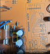
Please check the attached pictures and video with the noise, and suggest what else can I do. I really love this amplifier as it was originally from my father so I´d love to repair it.

Video with the noise


Thank you!

WhatsApp Image 2022-03-13 at 4.45.07 PM (1).jpegWhatsApp Image 2022-03-13 at 4.45.07 PM (2).jpegWhatsApp Image 2022-03-13 at 4.45.07 PM (3).jpegWhatsApp Image 2022-03-13 at 4.45.07 PM.jpegWhatsApp Image 2022-03-13 at 4.45.08 PM (1).jpegWhatsApp Image 2022-03-13 at 4.45.08 PM.jpegWhatsApp Image 2022-03-13 at 4.45.09 PM.jpegWhatsApp Image 2022-03-13 at 4.45.10 PM (1).jpegWhatsApp Image 2022-03-13 at 4.45.10 PM.jpeg
 

JeffS7444

Major Contributor
Forum Donor
Joined
Jul 21, 2019
Messages
2,366
Likes
3,555
I come to this forum seeking some help beyond my knowledge to resolve a weird issue I´m experiencing in my Luxman L-1 amplifier.
It has worked pretty well during his more than 30 years of life. However, quite recently, it creates a very frustrating noise in both Phono an Subsonic mode.
Are both L and R channels making the same noise?
 

LTig

Master Contributor
Forum Donor
Joined
Feb 27, 2019
Messages
5,833
Likes
9,573
Location
Europe
Could be one of the semiconductors in the phono preamp. Expecially if it appears on one channel only.
 
F

freemansteve

Guest
It's buggered. Possibly a blown cap, but it will probably be expensive to fix, in terms of labour cost...
After 30 years, buy something new, but be sure to recycle nicely....
 

sergeauckland

Major Contributor
Forum Donor
Joined
Mar 16, 2016
Messages
3,460
Likes
9,162
Location
Suffolk UK
It's buggered. Possibly a blown cap, but it will probably be expensive to fix, in terms of labour cost...
After 30 years, buy something new, but be sure to recycle nicely....
I disagree, not that it's not 'buggered', I would use the same word, but that it has to be expensive to fix. It should be a trivial repair for anyone technical, that doesn't have to make a living from repairs. I would be happy to repair it just for the pleasure and satisfaction of doing so, and I would expect there would be others local to the OP who would do the same. You just have to find them. Post where you're located and hope somebody responds.

S.
 
OP
L

LeinadPT

Member
Joined
Mar 13, 2022
Messages
7
Likes
0
Thanks all for your replies.
Yes, same noise in both channels.
I would like to see some options to repair, as I said this has happened all of a sudden, so I would like to try it before buying a new one!
Would you please suggest some concrete actions to check/try? Would be great also if you can indicate concretely in the pics.

Thanks all for your help!
 

sergeauckland

Major Contributor
Forum Donor
Joined
Mar 16, 2016
Messages
3,460
Likes
9,162
Location
Suffolk UK
Same noise in both channels is a good sign, as it indicates that the fault has to be common to both channels, so gives a hint of where to look on the circuit diagram.
First step is to get hold of a Service Manual that gives the full circuit together with voltages at the various points. Then, it's a relatively simple job of tracing through the circuit to find the fault. I can't give you a visual on the photos, as they don't show the circuit. You'll need a signal generator and oscilloscope, which any techie should have.

Edit:- Just downloaded the service manual from HiFi Engine. It's free, but you need to register.
There's a separate power supply for the phono stage, -45v on the emitter of Q301, so if you're getting something else there, that's where the fault is likely to be.

S
 
Last edited:
OP
L

LeinadPT

Member
Joined
Mar 13, 2022
Messages
7
Likes
0
Thanks sergeauckland,
I´ve downloaded the service manual and have located Q301. Unfortunately I don´t have a signal generator nor oscilloscope, but a multimeter that hopefully can help me to get some checks.

Attached I´ve sent a pic where Q301 is located, do you think I could try to get the output once powered on?
I´ve checked the S/N and it seems to be a PNP transistor, could you please indicate how to check for those -45v (I mean, what pins).

Thanks a lot.
 

Attachments

  • cYSIwUItRz.png
    cYSIwUItRz.png
    1.6 MB · Views: 52

sergeauckland

Major Contributor
Forum Donor
Joined
Mar 16, 2016
Messages
3,460
Likes
9,162
Location
Suffolk UK
A multimeter will be all you need if the problem is just in the phono stage power supply.

Put the positive lead from the multimeter somewhere on the amplifier chassis or zero volt point. You could stick the positive probe into the black -ve loudspeaker terminal as a convenient point.
With the negative probe on the multimeter, set to a suitable DC voltage range, measure o the three legs of Q301. You should measure well above 45v, possibly 50v, on one leg (the collector), around 45v on the emitter and 45.5v on the third leg (the base). I can't tell you which of the three legs is which, as I can't see the transistor on the image you sent. If the transistor is OK there will be 0.5v between base and emitter, 5-10v between emitter and collector. If you don't get these voltages, then it needs more investigation.
Start from the mains transformer secondary, that should be around 40v AC. Then follow the circuit of the power supply and note what the volts are. That should find the fault if it's in the power supply.

By the way, I take it you have checked the fuses, as fuse 301 feeds the phono power supply, so if that's blown, then the power supply won't work. If it's blown, replace it with a fuse of the exact same value. If that blows too, then you definitely have a fault in the power supply. If it doesn't blow and the amp now works normally, you've fixed it. Fuses do blow for no reason except age, fuses get a small thermal shock every time they're switched on and eventually metal fatigue causes them to rupture unexpectedly and with no obvious cause.

S
 
OP
L

LeinadPT

Member
Joined
Mar 13, 2022
Messages
7
Likes
0
Thanks again, sergeauckland.
Yes, all fuses were checked (that was my firsts check), and a bit of cleaning of dust in all parts inside (I could do it better with some specific product, but after hearing the noise I was under the impression that wasn´t dirty contacts related).

Will try this weekend all your recommendations in terms of multimeter voltage checks, hope it can reveal where the issue is!
Thanks, will keep you posted.

Regards,
Lein.
 

JayGilb

Major Contributor
Joined
Jul 22, 2021
Messages
1,384
Likes
2,355
Location
West-Central Wisconsin
Thanks again, sergeauckland.
Yes, all fuses were checked (that was my firsts check), and a bit of cleaning of dust in all parts inside (I could do it better with some specific product, but after hearing the noise I was under the impression that wasn´t dirty contacts related).

Will try this weekend all your recommendations in terms of multimeter voltage checks, hope it can reveal where the issue is!
Thanks, will keep you posted.

Regards,
Lein.
I would still clean all of the switch contacts using a plastic safe electrical contact cleaner such as Deoxit D5.
Also check for cracked solder joints on the bottom side of circuit boards in and around the phono preamp section.
 
OP
L

LeinadPT

Member
Joined
Mar 13, 2022
Messages
7
Likes
0
Hi guys,
I´ve just done the cleaning and the Q301 checks.

I´ve measured -110v between legs 1 and ground, and between leg 2 and ground, and -105 between leg 3 and ground:

1647886948522.png


As sergeauckland suggested, and confirmed by my own check in service manual, expected voltage there is -45v
(I guess this is just with the amplifier connected, regardless of a vinyl record being played, just to double check)

1647886787975.png


Does this ring a bell? Can the transistor itself be the reason about this over x2 voltage? Any additional checks?

Thanks again.
 

sergeauckland

Major Contributor
Forum Donor
Joined
Mar 16, 2016
Messages
3,460
Likes
9,162
Location
Suffolk UK
Can you measure the AC voltage coming out of the transformer (The two blue wires). There's something wrong with the DC measurements, as you say, they're about twice what they should be, so would like to be sure that the AC going to the half wave rectifier diode is correct.
Then, measure between ground and both sides of R303.

Make sure the meter is on the right voltage range and AC for the transformer measurement and DC for the R303 measurements.

S
 
OP
L

LeinadPT

Member
Joined
Mar 13, 2022
Messages
7
Likes
0
Hi sergeauckland,

I´ve done the suggested measurements with following results:

  • Two blue wires aka transformer AC output: 38.1v (yellow square in picture)
  • R33 far pin to transistor Q301 (blue circle in picture)-> AC: 112.9 v, DC: 51.6v
  • R33 close pin to transistor Q301 (red circle in picture)-> AC: 110.9 v, DC: 50.7v
1647962531240.png


Thanks again.
 

solderdude

Grand Contributor
Joined
Jul 21, 2018
Messages
16,051
Likes
36,427
Location
The Neitherlands
Q301 is a so called capacitance multiplier.
In essence the 100uF cap is multiplied by the gain of the Q301.
It should filter the DC ripple.

Perhaps one of the 100uF/50V caps is not 100uF anymore. I assume one of them is the reservoir cap and D305 its rectifier.

C of Q301 should be at least 1V above the E of Q301 and B should be about 0.5-0.6V higher than E.

I suggest to measure the DC voltages between these pins.
 

sergeauckland

Major Contributor
Forum Donor
Joined
Mar 16, 2016
Messages
3,460
Likes
9,162
Location
Suffolk UK
The 50.7 v at the output of R 303 is exactly what I would expect, so that indicates that the transformer and rectifier are OK. However, that doesn't tally with the measurements you previously provided around Q301. Have another go at measuring the DC voltage on the three pins of Q301, making sure you're measuring relative to ground, which is why I suggested using one of the black loudspeaker terminals for the meter + test lead.

You should get the -50.7 volts on one pin of Q301, (the collector) and the -45V on the emitter, with -45.5V or thereabouts on the third pin, (the base). If you don't get -45V on Q301, then either Q301 has failed, or less likely perhaps, one of the other components in that power supply section.

S.
 
OP
L

LeinadPT

Member
Joined
Mar 13, 2022
Messages
7
Likes
0
Hi guys,

Sorry have been a few days off.
Finally today I´ve re-checked in Q301 pins and here are DC results:

-49.1 v between pin 1 and ground
-48.7 v between pin 2 and ground
-51.3 v between pin 3 and ground
index.php


I think these values makes now much more sense, and are aligned with what to be expecting from user´s manual.
Not sure how to proceed further, to be honest :(
 
Top Bottom