• WANTED: Happy members who like to discuss audio and other topics related to our interest. Desire to learn and share knowledge of science required. There are many reviews of audio hardware and expert members to help answer your questions. Click here to have your audio equipment measured for free!

Unbranded ADC from eBay - measurements

I wonder whether the poor LF performance is due to small input coupling capacitors, assuming it has some! It seems odd to me for an ADC chip, of whatever cost, to be so poor a low frequencies. If so, then it's a cheap and quick fix.

S.
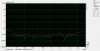
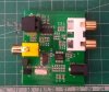
Took the ADC apart and took a few photos of the guts - can't really see all the traces clearly, but I'm assuming C8 and C9 might be the input coupling capacitors. Can't see any writing on the ADC chip either to check the datasheet :confused:
20210607_171106.jpg
20210607_172903.jpg
20210607_171145.jpg
20210607_172928.jpg
 
Lot of cold soldering
 
Last edited:
I wonder whether the poor LF performance is due to small input coupling capacitors, assuming it has some! It seems odd to me for an ADC chip, of whatever cost, to be so poor a low frequencies. If so, then it's a cheap and quick fix.

S.

probably a single cap value that needs to be increased. The designers chose to not use an opamp before the input and most likely just installed a too small coupling cap. Input R of the chip is 25k.
I guess the input cap needs to be increased a few factors.
I would assume the reference cap may also have a too small value.

input pins are 10 (L) and 12 (R)

1623252546054.png
 
Last edited:
As well as distortion, Amir's tests show poor frequency response, which I'm guessing is input coupling capacitors. I can't see the size of those chip capacitors, but if the ADC chip is the CS5340 (or a reject or a clone at that price) then, if I've done my maths right, a 25k input impedance and no buffer would need a coupling capacitor of around 630nF for a -3dB at 10Hz so good for -1dB at somewhere near 20Hz. 630nF doesn't sound unreasonable for a chip capacitor, so doubly surprised at the lack of LF.

S.
 
I have a similar ADC but it's branded "Goobay".
For optimum performance, the in put levels shouldn't exceed ~600mV RMS.
The frequency response of mine is ok, but rolls off a fair bit above 10kHz

This was tested as follows: DAC --> buffer with level control --> ADC --> DAC --> sound card.

Overall - not a bad result for a device that cost around £18

ADC is PCM1802 there is also a CS8406 'digital audio interface transmitter' and a 24.576 MHz crystal.

1623418421076.png


1623418458234.png

1623418873487.png

1623419433728.png
 

Attachments

  • 1623418885877.png
    1623418885877.png
    71.5 KB · Views: 157
  • adc.jpg
    adc.jpg
    857 KB · Views: 190
Last edited:
Thanks for posting the PCB pictures. I’ve ordered one and plan on trying some mods to improve the performance. It looks like the ADC chip is a Cirrus Logic (or copy) CS5340. I’m guessing that R3/C8 and R4/C9 are first order filters for the inputs instead of using the recommended op amp. My first mod would replace C8 and C9 with Wima film caps. Post #23 initially confused me. The graph is for a cap on the Filt+ pin, not the analog inputs. That would be my second mod. It looks like that would be C4 or C12. Patiently waiting for that slow boat….
 

Creative Sound Blaster X5 Hi-res 32bit/384kHz External USB DAC with Fully Balanced Xamp Headphone Bi-amp, Bluetooth Receiver, RCA in/-Out, TOSLINK Optical in/-Out, Mic-in, Headset-in for Audiophiles ​

 
Back
Top Bottom