• WANTED: Happy members who like to discuss audio and other topics related to our interest. Desire to learn and share knowledge of science required. There are many reviews of audio hardware and expert members to help answer your questions. Click here to have your audio equipment measured for free!

TPA 3255 450kHz output freq.

Dusty

Member
Joined
Feb 11, 2024
Messages
9
Likes
3
Location
Poland
Hello,

I'v bought on Aliexpress BRZHiFi X30Y amplifier with TPA3255 inside. It works well but it heats quite much with or without input signal and with or without output load. After a couple of minutes looks through went holes termo cam shows over 60-70*C even on heatsink. It is not expected behavior of class-D, especially since my other class-D TPA3118 is cold like a fish.

Oscilloscope plugged on outputs shows sine wave of 450kHz (TPA default clock) and 3Vpp amplitude. Input signal modulates this "carrier". It is quite strange behavior. My TPA3118 has flat line without signal and clear signal with.

Could somebody confirm or deny, is it normal behavior of TPA3255?
What is the most possible cause? I would like to know before I will start digging inside.
Maybe somebody could measure by oscilloscope outputs own TPA3255 amp?

THX.
 

IAtaman

Major Contributor
Forum Donor
Joined
Mar 29, 2021
Messages
2,409
Likes
4,165
Hello and welcome. Sorry it is a problem that brought you to ASR.

Where did you measure the 450K 3Vpp signal - at the speaker outputs? If that is the case, then something is definetely wrong. Maybe a short on the LC output filter?
 
Last edited:

mcdn

Addicted to Fun and Learning
Forum Donor
Joined
Mar 7, 2020
Messages
578
Likes
805
Typical noise levels at the speaker outputs for TPA3255 amps are 85microvolts. What you are seeing is grossly wrong and broken.
 

LSPhil

Member
Joined
Jan 26, 2024
Messages
17
Likes
13
Location
Niemcy
I also have a board like this with the same appearance. It's a scam.
 
OP
Dusty

Dusty

Member
Joined
Feb 11, 2024
Messages
9
Likes
3
Location
Poland
Typical noise levels at the speaker outputs for TPA3255 amps are 85microvolts. What you are seeing is grossly wrong and broken.

On TPA output pins (before low-pass filter, no BTL), without input signal, there's an 450kHz 50% square wave almost with supply rails voltage. Am I right? So, look below. I simulate TPA's low-pass filter in LTSpiece using real elements modeling by AD. There's at least tenfold more then you are talking about.

So, how is it possible achieve better result in reality? Is my simulation wrong?

1707763727762.png
 

Guddu

Addicted to Fun and Learning
Joined
Feb 10, 2020
Messages
853
Likes
721
Hello,

I'v bought on Aliexpress BRZHiFi X30Y amplifier with TPA3255 inside. It works well but it heats quite much with or without input signal and with or without output load. After a couple of minutes looks through went holes termo cam shows over 60-70*C even on heatsink. It is not expected behavior of class-D, especially since my other class-D TPA3118 is cold like a fish.

Oscilloscope plugged on outputs shows sine wave of 450kHz (TPA default clock) and 3Vpp amplitude. Input signal modulates this "carrier". It is quite strange behavior. My TPA3118 has flat line without signal and clear signal with.

Could somebody confirm or deny, is it normal behavior of TPA3255?
What is the most possible cause? I would like to know before I will start digging inside.
Maybe somebody could measure by oscilloscope outputs own TPA3255 amp?

THX.
Many TPA3255 amps reviewed here have less than 7-10 watts idle power consumption, which should barely make it warm to touch.
 

IAtaman

Major Contributor
Forum Donor
Joined
Mar 29, 2021
Messages
2,409
Likes
4,165
On TPA output pins (before low-pass filter, no BTL), without input signal, there's an 450kHz 50% square wave almost with supply rails voltage. Am I right? So, look below. I simulate TPA's low-pass filter in LTSpiece using real elements modeling by AD. There's at least tenfold more then you are talking about.

So, how is it possible achieve better result in reality? Is my simulation wrong?

View attachment 349216
There should not be a 50% square wave at the output with no input.
 

mcdn

Addicted to Fun and Learning
Forum Donor
Joined
Mar 7, 2020
Messages
578
Likes
805
@Dusty the figure I gave was for BTL operation with an AES17 filter, so probably not that helpful to you! See section 7.6 of the datasheet. The SE equivalent (still A-weighted with AES17 filter) is 160uV

SE operation does indeed create a 50% square wave at the output pins, and therefore DC offset after the LC filter, which is why a DC blocking cap is also required. See this rather readable design guide which uses the TPA3255 for many of its examples: https://www.ti.com/seclit/ml/sszp407/sszp407.pdf.

With BTL operation more clever modulation schemes are possible, but The TPA3255 uses basic AD modulation apparently (section3 of page 1 of the datasheet), so will also have a full signal square wave at the output pins when idle. This tech note from TI has nice explanations: https://www.ti.com/lit/an/snaa034a/snaa034a.pdf

In your case, you seem to have a broken filter in some way, which is allowing a significant signal through. A properly implemented TPA3255 is inside a vast range of very high quality and well reviewed amps!
 
OP
Dusty

Dusty

Member
Joined
Feb 11, 2024
Messages
9
Likes
3
Location
Poland

mcdn

Addicted to Fun and Learning
Forum Donor
Joined
Mar 7, 2020
Messages
578
Likes
805
Many thanks for this 2 links. I learned a lot.

BTL it is just my configuration. Now I am pretty sure my low-pass filter doesn't work as TI designed/predicted. But still can't modelling in LTSpice such low Vpp for 450kHz after low-pass filter as You've written before. How is it possible?
I found this excellent article at Audioholics which does the maths on typical residual switching noise, typical tweeter impedances, etc, and comes up with ~350mVrms and ~24mW of power being dissipated in the tweeter in that scenario: https://www.audioholics.com/audio-amplifier/switching-amplifier-class-d-basics

A simple simulation of the TPA3255 recommended output filter gives ~500mVrms of residual per half-bridge (at 48V PVDD so 24V per half bridge), not sure how correlated it would be: https://www.circuitlab.com/circuit/hhqtx3kdx3z8/switching-residual/ but in practice at these frequencies behaviour can be a bit different than the raw numbers suggest (I haven't got ESR in there for example). I have some well-executed modules in my cupboard (newish 3e-audio TPA3255 BTL), I'll test one later today perhaps.

Anyway the point is there's no way the switching residual should be burning power unless there is a major problem with the output LC filter
 
OP
Dusty

Dusty

Member
Joined
Feb 11, 2024
Messages
9
Likes
3
Location
Poland
Thanks for knowlage.

I will try made better low-pass filters. Just ordered ferrite rings. Wonder will it be lower 450kHz Vpp?
 
OP
Dusty

Dusty

Member
Joined
Feb 11, 2024
Messages
9
Likes
3
Location
Poland
Hi,

It's 10*C outside, raining. I've never seen weather like this in February. So it's time to dig.

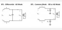
I decided to modify output filters step-by-step to see changes. First changed filters from "common mode" to "differential", because it was the simplest change I could made.
typy_filtrów.JPG

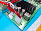
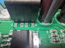
Removed 1uF SMD capacitors but left original inductors (measure 9,8uH)...
01.jpg02.jpg

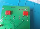
... and mounted in the opposite side two 1uF WIMAs in differential mode.
03.jpg

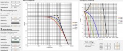
Simulation shows a little ringing above 10kHs and about 0,5dB on 6ohm and more loads, but who as I almost 60 cares?
charki.JPG

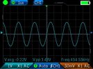
And of course measurements. Before was 3,43 Vpp measured on 8R2 resistors:
img_01.jpg

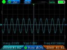
and now is... 0,58Vpp! WOW!
img_02.jpg


For sure better inductors 12uH-15uH should improves this result. But for now, I'm really lost all my motivation to make any more changes...

...or maybe....
 
Last edited:
OP
Dusty

Dusty

Member
Joined
Feb 11, 2024
Messages
9
Likes
3
Location
Poland
you could increase pwm

What's simple and brillant idea, thx! I'm dumb.

BTW. Higher frequency means more losses in ferrite. What's the temperature of ferrites especially not yours Aiyama? Is it rise?
 
OP
Dusty

Dusty

Member
Joined
Feb 11, 2024
Messages
9
Likes
3
Location
Poland
Amplifier was closed.

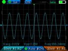
End result: 595kHz, 0,25Vpp.
img_01.jpg

Thx for advice. Best regards.
 

babadono

Member
Joined
Jul 8, 2021
Messages
57
Likes
12
@Dusty
Wow wish I would have seen this earlier....Although only been about a month. I built a DIY amp based on the TI eval board of the 3255. And yes I have about 2Vpp at 450k(or is it 455?) when loaded with 4 ohm load resistors. So putting better quality capacitors in the output filter is what made it better? Also you upped the operating frequency? That might be tricky on the eval board....
 
Top Bottom