• WANTED: Happy members who like to discuss audio and other topics related to our interest. Desire to learn and share knowledge of science required. There are many reviews of audio hardware and expert members to help answer your questions. Click here to have your audio equipment measured for free!

SMPS for Audio Applications

audio2design

Major Contributor
Joined
Nov 29, 2020
Messages
1,769
Likes
1,830
I don't have any plot yet, to be honest, but it is low to the level it's not disturbing any sensitive device around it.

- no offence but that is completely meaningless. I have had things on the bench 30db above Class A that did not disturb devices nearby ... But that is only because I didn't have the right devices nearby.


I don't have any measures for THD yet, Power factor is 98% @ 110VAC & 99% at 240VAC.

What power level related to full power are these measurements at? These results are unlikely properly measured. PF is rarely better at high voltage.


- most SMPS are not selectable these days but simply work over a wide input voltage range. What range do yours work over?


ZCS

- ZCS is not an architecture. It is a technique within an architecture. What is the power supply topology?

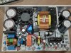
65KHZ & maximum 71KHZ, FYI no synchronous rectifier

- this seems very low frequency. Perhaps for the first stage but for the secondary very low given the power and transformer size.

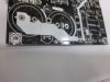
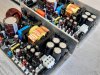
don't worry too much about creepage distances because I take care of them really well with an additional 3mm airgap between primary and secondary, also were needed at some specific locations at the primary side.

I do worry as shocking customers is bad for business.. You use the same metal heatsink for input and output semiconductors and the pins are very close to the heatsink. That may result in a spacing violation. That makes me worry about other creepage and clearance differences.
 

restorer-john

Grand Contributor
Joined
Mar 1, 2018
Messages
12,580
Likes
38,281
Location
Gold Coast, Queensland, Australia
For the record, here is microaudio's post that seems to have disappeared....

1606742634963.png
 
OP
MicroAudio

MicroAudio

Active Member
Audio Company
Joined
Mar 27, 2020
Messages
143
Likes
208
Location
AMMAN - JORDAN
With respect to you and your efforts, I think this discussion will go nowhere.


I will follow your advice and add extra isolation for the power device pins on the next revision of the SMPS, while there is 3mm air gap between the PCB and the heatsink.

I also don’t understand whats the problem with the power factor of 0.99% or 0.94%? if you don’t believe it, its up to you I am not selling lies to my clients my friend.


These results are unlikely properly measured. PF is rarely better at high voltage “ Maybe you had experience with other manufacturers who lie, but I don’t.


I also don’t understand whats the problem running the SMPS at 65KHz or 40KHz? I can run the SMPS at 130KHz but 67KHz is the point where I want it.


When I release the next revision soon I will post pictures of creepage and isolation distances in front of everyone here to show how safe it is


I sold over 190 SMS units and I never had any single safety issues during the past years.

HYPEX and MANY other manufacturers are using the same metal heatsink for the power devices without providing any special isolation for the power devices, and I don’t see any post from your side asking the same questions to them for example.


It would be great if you open a thread at some other place and ask the same questions to others, and I am really interested in the results.

So, to finalize things

There are many unclear questions from your side that looks too complex for me to answer, and I don’t have measurements to display at this time.


Thank you very much.
 
OP
MicroAudio

MicroAudio

Active Member
Audio Company
Joined
Mar 27, 2020
Messages
143
Likes
208
Location
AMMAN - JORDAN
Post deletion was to add the pictures to it and make it more organized.
20201130_155243 (2)-min.jpg
20201130_155329 (2)-min.jpg
20201130_155243 (2)-min.jpg
20201130_155551 (2)-min.jpg
20201130_155559-min.jpg


For the distance and creepage of the power devices, below some pictures of the distance and insulators used.
20201130_155243 (2)-min.jpg20201130_155329 (2)-min.jpg20201130_155544-min.jpg20201130_155551 (2)-min.jpg20201130_155559-min.jpg
20201130_155243 (2)-min.jpg
20201130_155329 (2)-min.jpg
20201130_155544-min.jpg
20201130_155551 (2)-min.jpg
20201130_155559-min.jpg
 

audio2design

Major Contributor
Joined
Nov 29, 2020
Messages
1,769
Likes
1,830
If 190 units that sounds like more than friends and you are promoting it here which is well beyond your "friend" group. Anything AC must be taken seriously. What is safe one day gets into a high humity location for a few years and suddenly no longer is.


WRT PF/THD that comes from knowledge of what drives those specs and why I question the numbers.


WRT frequency that comes from looking at transformer size versus frequency and thinking about realistic limits. What works fine at room temp and center of distribution can be saturation at high temp and ends of the distribution.


Your answer to my question on topology and/or architecture was not an engineering answer. Not even close. That makes me question whether you designed these supplies.
 

audio2design

Major Contributor
Joined
Nov 29, 2020
Messages
1,769
Likes
1,830
P.s. in your pictures those are metal stand- offs and a metal ring. That metal ring appears to be almost touching where the bulk caps on the AC side are. Looking at other pics the caps extend out to the large circle.
 
OP
MicroAudio

MicroAudio

Active Member
Audio Company
Joined
Mar 27, 2020
Messages
143
Likes
208
Location
AMMAN - JORDAN
If 190 units that sounds like more than friends and you are promoting it here which is well beyond your "friend" group. Anything AC must be taken seriously. What is safe one day gets into a high humity location for a few years and suddenly no longer is.

190 Units sold from the entire range, not the SMPS1k_PFC, models were not shown here.
And I believe that this location where I am posting is to sell products I think?

190 units were not sold here. sold here much less than that.


WRT PF/THD that comes from knowledge of what drives those specs and why I question the numbers.

I will post more data on that matter specifically soon.


WRT frequency that comes from looking at transformer size versus frequency and thinking about realistic limits. What works fine at room temp and center of distribution can be saturation at high temp and ends of the distribution.


Your answer to my question on topology and/or architecture was not an engineering answer. Not even close. That makes me question whether you designed these supplies.

Not answering your question properly never means that I am not the designer.
 
OP
MicroAudio

MicroAudio

Active Member
Audio Company
Joined
Mar 27, 2020
Messages
143
Likes
208
Location
AMMAN - JORDAN
P.s. in your pictures those are metal stand- offs and a metal ring. That metal ring appears to be almost touching where the bulk caps on the AC side are. Looking at other pics the caps extend out to the large circle.

No, I will post some pictures from ALTIUM later today to show you that it is far away from that, the TOP silkscreen is not showing the PCB tracks.

Thanks!
 

audio2design

Major Contributor
Joined
Nov 29, 2020
Messages
1,769
Likes
1,830
The pictures of the insulators you just posted do not match those of the images of the completed supplies on the first page.
 

audio2design

Major Contributor
Joined
Nov 29, 2020
Messages
1,769
Likes
1,830
For regulatory, the aluminum case of a electrolytic cap is live. The metal standoff and PCB ring which ground to the case are close to the aluminum case. The plastic wrap on a e-cap is not a sufficient insulator for regulatory purposes.
 

audio2design

Major Contributor
Joined
Nov 29, 2020
Messages
1,769
Likes
1,830
Not answering your question properly never means that I am not the designer.


... 30 years in engineering, management and ownership has taught me that the depth and quality of answers is a great indicator of actual involvement.
 
OP
MicroAudio

MicroAudio

Active Member
Audio Company
Joined
Mar 27, 2020
Messages
143
Likes
208
Location
AMMAN - JORDAN
For regulatory, the aluminum case of a electrolytic cap is live. The metal standoff and PCB ring which ground to the case are close to the aluminum case. The plastic wrap on a e-cap is not a sufficient insulator for regulatory purposes.

I really like the discussion with you indeed, what you are saying is 100% correct and for that specific reason, I add an additional layer of insulating tape underneath the capacitors as shown attached.

I hope that someone else could post a picture close enough from the SMPS1K-PFC to show that ALL the primary area has that layer underneath the CAPACITORS.

Thanks!
 

Attachments

  • PCB-1-min.jpg
    PCB-1-min.jpg
    706.8 KB · Views: 261
OP
MicroAudio

MicroAudio

Active Member
Audio Company
Joined
Mar 27, 2020
Messages
143
Likes
208
Location
AMMAN - JORDAN
Not answering your question properly never means that I am not the designer.


... 30 years in engineering, management and ownership has taught me that the depth and quality of answers is a great indicator of actual involvement.


To be honest, that answer from my side for the (technique& architecture ) looked unmeaningful. I apologize
 
OP
MicroAudio

MicroAudio

Active Member
Audio Company
Joined
Mar 27, 2020
Messages
143
Likes
208
Location
AMMAN - JORDAN
If you don't see the tape in some images, because there is another method used to make that additional insulation as shown below.

I made this now for your reference only to show you how it's made.
 

Attachments

  • 20201130_164908-min.jpg
    20201130_164908-min.jpg
    483 KB · Views: 219
OP
MicroAudio

MicroAudio

Active Member
Audio Company
Joined
Mar 27, 2020
Messages
143
Likes
208
Location
AMMAN - JORDAN
If 190 units that sounds like more than friends and you are promoting it here which is well beyond your "friend" group. Anything AC must be taken seriously. What is safe one day gets into a high humity location for a few years and suddenly no longer is.


For that exact humidity reason, I am using the additional tape underneath the capacitors & and an additional method to spray all parts / PCB tracks underneath the PCB to prevent that from happening.

If you also noticed that the TRACK underneath the capacitors on the TOP layer of the PCB is also covered with the silkscreen layer for additional protection. also the 1mm air gaps near the AC NETS in the same picture.

Thanks
 

audio2design

Major Contributor
Joined
Nov 29, 2020
Messages
1,769
Likes
1,830
Critical distance:

1606749707980.png


It would be best to extend the insulator below the PCB. Not sure what is on the back.

1606749769373.png


The black plastic on the capacitor is not a UL barrier.

1606749830057.png


Hence the ring around the mounting hole, which is the chassis, is very close.

1606749982751.png


These insulators, as noted, do not go nearly as far down as the new ones you showed.
 
OP
MicroAudio

MicroAudio

Active Member
Audio Company
Joined
Mar 27, 2020
Messages
143
Likes
208
Location
AMMAN - JORDAN
Everything you have mentioned is already done to all SMPS models already last month.

And SMPS1K-PFCR2 will reflect that directly once released.

For the rings, all holes on the PCB are replaced with no metal ring, just a hole for the screw + added 1mm air gap cut in the PCB to that area specifically in that model.

All insulators updated in all the revisions, also the new ones will have a full insulator cap to cover the whole device.


Also, there will be an additional insulation layer underneath the SMPS1K-PFCR2 as the standoffs will be 5mm to match 50mm total height.

Also, there will and an additional layer of insulation tape behind the power devices.

If you have any other improvements like the ones you have already mentioned please indicate them so I can implement them.

Thank you
 

Attachments

  • i-to247-cap.jpg
    i-to247-cap.jpg
    5 KB · Views: 114
OP
MicroAudio

MicroAudio

Active Member
Audio Company
Joined
Mar 27, 2020
Messages
143
Likes
208
Location
AMMAN - JORDAN
SMPS500-CLA for CLASS-A Amplifiers with +-25VDC and 2.8A total continuous current.

The SMPS takes up to 60000uF of extra capacitance per rail.

DC Error
StandBy
+-15VDC
Delay output
 

Attachments

  • 20201004_181349-min.jpg
    20201004_181349-min.jpg
    740.2 KB · Views: 163
Top Bottom