• WANTED: Happy members who like to discuss audio and other topics related to our interest. Desire to learn and share knowledge of science required. There are many reviews of audio hardware and expert members to help answer your questions. Click here to have your audio equipment measured for free!

Small 2-way speakers with linear on-axis and power response characteristics (Scan Speak and SB Acoustics drivers). H&V off-axis measurements included

What do you think about a dual amp solution where the C-R-L part is made into a sallen key RC filter with between -8 to -12 dB gain?
The amp could be about 1/10 of the watts compared to the LF amp.
The 2 uF could be there at speaker protection/ 6dB oct filter + easier to make 2. order active filter than 3. order active filter
I'm not sure if I'm getting your idea but isn't this an unnecessarily complication?
 
I have re-merged the measurements with the following result (red: gated/NF with VituixCad crossover simulation, gray: Klippel NFS).
M23_NFS_vs_gated&NF_remerged.png

Still not 100% perfect but much better.
I used diffraction response according to the guidelines in the PDF and a bit different approach to BR port response scaling.
 
Last edited:
I'm not sure if I'm getting your idea but isn't this an unnecessarily complication?
It is an complication if number of watts from amp is unlimited. But if amp can be driven to max it is better to have two smaller ones. Then the bass can be distorted but the hf will be clean.
And the hf amp could be really small.
You could go digital DSP. But then you have extra delay.
 
For the DIY first-timers, consider buying and assembling the Parts Express C-note kit and use Xmechanik's mechano22 crossover. Add a simple crossbrace and some damping to the cabinet while you're at it. I think you'd end up with a similarly impressive resulting project.
That's an interesting idea. Has this been attempted by anyone? The cabinet is slightly different for the mechano22 but it seems like it'd even out a lot of the issues with that speaker.
 
For the DIY first-timers, consider buying and assembling the Parts Express C-note kit and use Xmechanik's mechano22 crossover. Add a simple crossbrace and some damping to the cabinet while you're at it. I think you'd end up with a similarly impressive resulting project.

A first time DIYer would be better off building the C-Note as-is. The Mechano22 has a different size baffle, driver positions and CTC distance than the C-Note. This means the driver measurements are not the same and the rather complex crossover would need to modified. The C-Note crossover is a much simpler crossover for a novice to comprehend and gets a decent result too.

Making the leap from building to designing speakers is a big investment in equipment and learning. Tools like XMachina and VituixCAD are lowering the bar to optimize speaker designing. They can help get you to a faster result. However, a good outcome from those tools still requires disciplined driver measurements and a solid foundation in filter design. Without those skills, you are simply likely to more quickly create a very flawed speaker.
 
The user also need control of the individual speaker measurements and components to get the perfect result.
It is made of 5% tolerance parts and a lot of them. So if unlucky the result could be less than stellar.
So maybe not for the first timer without messurement knowledge
 
Basically saying the page doesnt exist.
Trying to clarify some issues with google drive that flagged zip file with the software. Since this happened 8 months ago and I have no idea how to make any progress, it may never get resolved I'm afraid.
 
One more comparison of Klippel vs. gated/NF: Estimated In-room Response (red: gated/NF with VituixCad crossover simulation, gray: Klippel NFS)
M23_remerged_PIR_NFS_vs_gated&NF.png

Good matching overall (after re-merging the measurements), just a remark that in the 70-290Hz range error gets systematic (gateted/NF over-prediction) but the error level is rather small, 1dB or less.
 
^Tiny part of the difference in SP and PIR tilts could come from different angle weighting factors for sound power calculation. VituixCAD gives a bit less HF to off-axis averages than with factors published in CTA2034-A (Klippel could use). I can compare results with different factors in debug mode.
CTA2034A angle weighting for SP.png

VituixCAD angle weighting for SP.png
 
Trying to clarify some issues with google drive that flagged zip file with the software. Since this happened 8 months ago and I have no idea how to make any progress, it may never get resolved I'm afraid.
Any chance you can share your software some place else? I would really like to try it, looks awesome
 
I used diffraction response according to the guidelines in the PDF and a bit different approach to BR port response scaling.
How far you simulated diffraction loaded to LF part in Merger? Distance affects quite much to LF level in Diffraction tool, because simulation sums direct and diffracted pressures without squaring, and higher than 1st order diffraction is not included. Recommendation is 5-30 m, but I usually set 10-30 m to ensure that simulation shows full baffle loss (to avoid too high level at LF during XO simulation).
 
How far you simulated diffraction loaded to LF part in Merger?
If I noted it correctly in the file name, it was 30m.

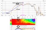
btw, tracing potential sources of errors I noticed that far field characteristics that I measured have sometimes strange behavior in the low frequency range. I ignored it because this part of the characteristic was supposed to be cut off and replaced with processed NF characteristic. But the merging result is clearly affected by the LF artifact on the far field measurements which is puzzling as it's outside the blending range. Any hint on this?
FF_LF_part_impact_on_mrg2.png
 
Last edited:
Sorry brain fart!:facepalm:
I started last night writing about the minimal port area thinking, it's DIY, so people are free to adjust the dimensions…
Then this morning reading the comments about the difficulties to get the job done I though I should try to find something with a minimal amount of modifications.
I got distracted...

Still, the idea is to add one panel on the back;) not necessarily just 18mm, 22mm (or more) works too,
Then relocating the ports might work even if it means cutting a bit of the plastic flange.

This the front view but the ports are at the back, the two circles are 45mm in diameter
They would need to move towards the center line of the speaker by a small amount in real life.
The length is OK with the added thickness, by hollowing out a good portion of the existing back panel the volume stays about the same.

Someone would have to double check though as I have been known to make mistakes.


View attachment 367348

Anyways, I’d rather redo the box to have a better port and LF performance.
The other way around is just increase the volume a little, say to 10L and increase the depth. Hopefully port(s) with larger dia/area and appropriate length will fit. Since we have larger volume we can move the fb up and reduce the length of the port(s) a little, but that may not be enough. The other option is to use 45° or 90° bend. Not too many options left.
 
I ignored it because this part of the characteristic was supposed to be cut off and replaced with processed NF characteristic. But the merging result is clearly affected by the LF artifact on the far field measurements which is puzzling as it's outside the blending range. Any hint on this?
Directivity in far field measurements is used also below transition frequency (down to 5 Hz) to get smooth transition in directivity, power etc. Measured directivity enables blending within 1/2...1 octave. Processed LF response with simulated directivity could require very wide blending range such as 4 octaves, but DI, magnitude and phase responses could still show some step at transition range. Simulated directivity added to NF data could be very okay for example with good symmetrical dipoles, but measured directivity rules with conventional boxed designs.

Possible problem with measured directivity is that LF noise could damage response at LF causing damage to directivity information. Some reflections too. Right after 0-180 deg measurement sequence it's recommended to convert IRs to FRs, scroll responses in 'Convert IR to FR' or load converted responses to Drivers tab, draw one wire to XO and verify with Directivity chart that all measurements are within acceptable tolerance at LF. If some individual off-axis response is bad, wait for silent moment (elephant stops jumping upstairs) and re-measure bad angle. Repeat until succeeded. Less good options are to remove response from the list and let program interpolate, or copy better nearest response with new filename.
Shallow window functions such as Hanning have better tolerance for LF noise than steep suct as Tukey 0.25 (but eliminating LF noise is not the main task of window function). You can also test whether "DC offset" checkbox in Convert IR to FR helps. It's nowadays re-enable also for CLIO mls and crp files, though it's not usually needed.

The last action to eliminate remaining directivity at very low frequencies is to use "Force to gradient" with Merger. Frequency to ca. Helholtz/system responance and Monopole portion 100% with box speakers. That drops DI to 0 dB.

PS-1: Earlier ARTA versions were quite problematic at LF due to inadequate delay between opening of measurement channel and beginning of sweep/periodic noise. The last ARTA should be as good as CLIO, assuming that input of soundcard does not have DC offset or hum.
PS-2: Designing FIR XO requires very good S/N at LF, and probably response trimming too. Data processing for passive XO project is much easier.
 
You can also test whether "DC offset" checkbox in Convert IR to FR helps.
This seems to work best with the problem. For example here's DC-offset compensation result for the worst sweep in the series:
DC_offset_works.png

I think I'll re-process the data again starting from converting IR to FR.
Many thanks for your detailed and useful answers!
 
Directivity in far field measurements is used also below transition frequency (down to 5 Hz) to get smooth transition in directivity, power etc. Measured directivity enables blending within 1/2...1 octave. Processed LF response with simulated directivity could require very wide blending range such as 4 octaves, but DI, magnitude and phase responses could still show some step at transition range. Simulated directivity added to NF data could be very okay for example with good symmetrical dipoles, but measured directivity rules with conventional boxed designs.

Possible problem with measured directivity is that LF noise could damage response at LF causing damage to directivity information. Some reflections too. Right after 0-180 deg measurement sequence it's recommended to convert IRs to FRs, scroll responses in 'Convert IR to FR' or load converted responses to Drivers tab, draw one wire to XO and verify with Directivity chart that all measurements are within acceptable tolerance at LF. If some individual off-axis response is bad, wait for silent moment (elephant stops jumping upstairs) and re-measure bad angle. Repeat until succeeded. Less good options are to remove response from the list and let program interpolate, or copy better nearest response with new filename.
Shallow window functions such as Hanning have better tolerance for LF noise than steep suct as Tukey 0.25 (but eliminating LF noise is not the main task of window function). You can also test whether "DC offset" checkbox in Convert IR to FR helps. It's nowadays re-enable also for CLIO mls and crp files, though it's not usually needed.

The last action to eliminate remaining directivity at very low frequencies is to use "Force to gradient" with Merger. Frequency to ca. Helholtz/system responance and Monopole portion 100% with box speakers. That drops DI to 0 dB.

PS-1: Earlier ARTA versions were quite problematic at LF due to inadequate delay between opening of measurement channel and beginning of sweep/periodic noise. The last ARTA should be as good as CLIO, assuming that input of soundcard does not have DC offset or hum.
PS-2: Designing FIR XO requires very good S/N at LF, and probably response trimming too. Data processing for passive XO project is much easier.
Kimmo, I don't know if I ever asked if you work in acoustics professionally? I've learned so much from your comments over the years.
 
Trying to clarify some issues with google drive that flagged zip file with the software.
You might try changing file extensions before zipping. This has been successful for me in the past. Of course the file extensions would have to be changed back before use.
 
If I were to start from scratch I would redraw the box to have indeed 8L net tuned to 51-53Hz but with a larger port that meets the 5% of speed of sound criterion even at max excursion.
The cabinet would have to be larger, the depth would definitely need adjusting to both accommodate the longer port and achieve the 8L target.
Height (increased towards the "bottom") could also be adjusted if required be adjusted with minimal impact on the response.
I've attempted to model larger enclosures in WinISD and VituixCAD, but it seems difficult to scale the design to 8l net (with the port at 52Hz) without either:
a) changing the width of the baffle
b) overlapping multiple resonance frequencies

Screenshot 2024-05-30 005100.png
Screenshot 2024-05-30 004824.png


Even with a much more generous sizing at 9.2l the issue remains (though the overlaps occur at higher frequencies).

The goal here would be to reduce distortion at a higher output (96dB) relative to the base design, so I'm concerned about the impact of these resonances at higher volumes. I don't have any experience designing speakers though, so perhaps it's less of a problem than I think it is.

Would there be any downsides - other than reducing output below 50Hz - to adopting a tuning frequency above 54Hz with an ~8-8.5l volume? The distribution of modes seems more favorable to me:

Screenshot 2024-05-30 004015.png

The extra output above 50Hz also suits my goals, and the 5% criterion for the port is easily met at 96 dB:
Screenshot 2024-05-30 010715.png
Screenshot 2024-05-30 010952.png
 
Back
Top Bottom