• WANTED: Happy members who like to discuss audio and other topics related to our interest. Desire to learn and share knowledge of science required. There are many reviews of audio hardware and expert members to help answer your questions. Click here to have your audio equipment measured for free!

Small 2-way speakers with linear on-axis and power response characteristics (Scan Speak and SB Acoustics drivers). H&V off-axis measurements included

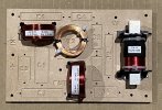
Okay, finally got all my parts in. Would appreciate it if anyone could verify my crossover wiring. Arrows just indicate left or right wire of each component .

Thanks in advance!

View attachment 392145
The wiring looks ok, except the place marked with question mark. It seems that tweeter coil (0.39mH) is shorted an grounded (or maybe I'm not reading wires correctly).
xo_m.jpg

It also seems that some of your descriptions are misplaced, for example the yellow box ("27uF+8.+1.5mH+18uF") contains woofer filter components but it points to the tweeter filter.
 
The wiring looks ok, except the place marked with question mark. It seems that tweeter coil (0.39mH) is shorted an grounded (or maybe I'm not reading wires correctly).
View attachment 392704
It also seems that some of your descriptions are misplaced, for example the yellow box ("27uF+8.+1.5mH+18uF") contains woofer filter components but it points to the tweeter filter.
Thank you for your review! I haven't seen a circuit diagram since high school physics so super helpful.

For the yellow box, you're right. I flipped the image to mirror the top down pic of the crossover and must've mixed up the labeling when I did that.

For the tweeter, the 0.39mH coil I connected to the ground of woofer filter, I'm not sure if that's good practice or if I should leave it as it's own. I have the ground wire of the coil going over the tweeter filter connection and so it looks like they're touching, but I'll insulate it.
 
Yep, a speaker design is nothing if not a series of trade-offs and compromises!

I just ran some tests with both L3 and L4 mounted in their designated places on my PCB and measured inductance using LIMP :

L3 (nominal value 1.5mH) : 1.52mH
L4 (nominal value 0.39mH) : 0.39124mH

Sum of measured values : 1.91124mH

L4 and L3 measured in series (nominal value 1.89mH) : 1.94mH => error of ~1.5% (versus sum)
All values measured @1KHz.
 
Last edited:
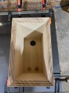
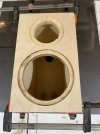
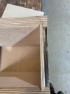
Progress photos on cabinet build. I can't take credit for these. A talented cabinet maker friend is kindly doing them for me. Finish will be 2 pack clear coat.

IMG_1156.jpg
 

Attachments

  • IMG_1157.jpg
    IMG_1157.jpg
    187.8 KB · Views: 177
  • IMG_1161.jpg
    IMG_1161.jpg
    257.9 KB · Views: 188
  • IMG_20240919_151441.jpg
    IMG_20240919_151441.jpg
    246.8 KB · Views: 190
Thinking this speaker would be great with a separate bass module underneath. I was just looking at Paul Carmody’s Tarkus where he uses the 10” Peerless SLS 830668 which is $59.50 at Madisound right now.

 
Thinking this speaker would be great with a separate bass module underneath. I was just looking at Paul Carmody’s Tarkus where he uses the 10” Peerless SLS 830668 which is $59.50 at Madisound right now.


Agree, even sealed, the SB woofer is up to the task and you get great power response that is not clear whether Tarkus delivers.
 
Any chance you'd be willing to sell a couple of the crossover boards?

The PCB is still to be verified as fit for purpose. Hopefully in a few weeks if I get the cabinets soon. I wasn't planning on selling any. Just doing it for the community. If the prototype verifies as ok I will probably look at setting up a public account on jlcpcb or similar so that people can order themselves.
 
Last edited:
I've finished my build. They're really good. Amazing sound for such a small speaker. Thanks @XMechanik

View attachment 396514
Nice cabinetry! I'm thinking of making a second pair with mitered joinery like this. First pair will be in our family's east-coast farmhouse kitchen, second pair for home in CA.

Slightly brighter in the midrange, slightly muddier mid-bass at high volume than my Philharmonic 3-ways, but wonderfully clear voicing. Amazingly good for the price and super fun to build.

@XMechanik great job, and I'm hoping you'll push to a tower for your next set of experiments!!!
 
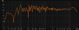
I did some measurements this morning using REW. I haven't done this for a while so I used this guide :


Microphone was minidsp umik-1 vertically pointed towards ceiling. The tip of the microphone was on the tweeter axis and about 50cm from the mechano23. I measured both speakers (L and R) in the same position. Correlation between the 2 mechano23s seems good. Does this seem about right given room effects?

both L and R SPL.jpg
 
frdcmpw.png

That's great you're trying to verify the results wit measurements. I've overlaid your measurement on my characteristic and I've noticed a wide dip in the 2.5-5.5kHz region. It seems too shallow to be an effect of bad driver polarity but that's worth checking anyway: both drivers should have their black connector grounded. I've no experience with rew and I haven't tried this moving mic method, so I'm not really sure if the difference is due to the method or potential problems. Isn't it possible to make quasi-anechoic (gated) measurement with rew? In a typical living room conditions you should get accurate characteristic for >300Hz.
 
View attachment 396970
That's great you're trying to verify the results wit measurements. I've overlaid your measurement on my characteristic and I've noticed a wide dip in the 2.5-5.5kHz region. It seems too shallow to be an effect of bad driver polarity but that's worth checking anyway: both drivers should have their black connector grounded. I've no experience with rew and I haven't tried this moving mic method, so I'm not really sure if the difference is due to the method or potential problems. Isn't it possible to make quasi-anechoic (gated) measurement with rew? In a typical living room conditions you should get accurate characteristic for >300Hz.

Thank you very much for this feedback. I shall investigate further doing quasi anechoic gated measurements. Pretty sure driver polarity is correct but I'll double check. Thanks.
 
Thank you very much for this feedback. I shall investigate further doing quasi anechoic gated measurements. Pretty sure driver polarity is correct but I'll double check. Thanks.
Any update on the potential public account to source the pcb? Thanks and your build looks great!
 
View attachment 396970
That's great you're trying to verify the results wit measurements. I've overlaid your measurement on my characteristic and I've noticed a wide dip in the 2.5-5.5kHz region. It seems too shallow to be an effect of bad driver polarity but that's worth checking anyway: both drivers should have their black connector grounded. I've no experience with rew and I haven't tried this moving mic method, so I'm not really sure if the difference is due to the method or potential problems. Isn't it possible to make quasi-anechoic (gated) measurement with rew? In a typical living room conditions you should get accurate characteristic for >300Hz.

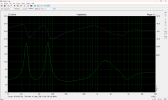
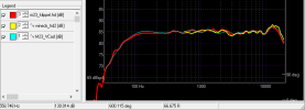
Not 100% sure this is done right but I think it looks better than last time. Here is a sweep from REW at 1m :

test.jpg


And with an IR window applied @2ms which I think corresponds to a quasi anechoic gated measurement :

test1.jpg


Interesting that I can see similarities to Amir's measurement - namely the little dip at 3kHz and the peak around 13.5kHz.
 

Attachments

  • test.jpg
    test.jpg
    82.4 KB · Views: 24
Any update on the potential public account to source the pcb? Thanks and your build looks great!

Thanks. I contacted the PCB vendor (JLCPCB) and they said a public account was not possible. If anyone knows otherwise I'm all ears. However its not that hard to order yourself. Just setup an account and upload the RAR file. With fastest shipping I had them in just over 4 days. I have uploaded the files and link to JLCPCB ordering instructions to github here :


1728687452290.jpg
 
Last edited:
Not 100% sure this is done right but I think it looks better than last time. Here is a sweep from REW at 1m :

View attachment 398154

And with an IR window applied @2ms which I think corresponds to a quasi anechoic gated measurement :

View attachment 398156

Interesting that I can see similarities to Amir's measurement - namely the little dip at 3kHz and the peak around 13.5kHz.
Now your measurement looks really good. It's indeed very consistent with the Klippel measurement Amir took for the review: (curves shifted for best overlap).
frdcmp2.png
Did you measure both pieces?

Thanks for sharing the PCB, if I happen to build another pair I'll probably use that too.
 
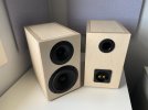
A quick update from Australia on the men's shed speaker project. We finally got the Mechanix23s assembled last weekend since I had to travel from Sydney to Melbourne to work with a friend who kindly offered to do the crossovers on a pre-printed MDF board.

Now built! Measurements also complete and looking very close to the original, will post these shortly. We are keeping with the butt joint build since they will be easier for shed members. They sound superb, a well-balanced rich sound with deep bass that can be adjusted based on speaker position and a honey-like treble. Lovely sound-staging too. We measured two damping options and found wool felt lining all walls better than loose stuffing. Need to make some speaker grilles since the soft-dome tweeter is at risk of finger-poking...Working now on an illustrated construction manual for builders which I'm happy to post here in due course if it's of help. Will commence demonstrations to a few men's shed in the area soon. Thanks again XMechanik for an outstanding design!
 

Attachments

  • Mechanix Display Front and Rear copy.jpg
    Mechanix Display Front and Rear copy.jpg
    128.3 KB · Views: 145
  • Screenshot 2024-10-13 at 3.35.39 pm.jpg
    Screenshot 2024-10-13 at 3.35.39 pm.jpg
    371.5 KB · Views: 146
Now your measurement looks really good. It's indeed very consistent with the Klippel measurement Amir took for the review: (curves shifted for best overlap).
View attachment 398465
Did you measure both pieces?

Thanks for sharing the PCB, if I happen to build another pair I'll probably use that too.

No I only measured one this time. If you look carefully at the first measurement I posted it was of both overlaid. In that measurement response of both speakers was almost identical.
 
Back
Top Bottom