• WANTED: Happy members who like to discuss audio and other topics related to our interest. Desire to learn and share knowledge of science required. There are many reviews of audio hardware and expert members to help answer your questions. Click here to have your audio equipment measured for free!

Room equalization through inverse delayed and attenuated bass signals

ozzy9832001

Senior Member
Joined
Feb 19, 2023
Messages
405
Likes
257
Can you provide a screenshot of REW Room Sim that reflects the above room and sub positions, including any adjustments to phase/delay/gain?

Edit: The effect of a room mode on the listener is dependant upon the listening position. In some spots there can be massive gain, in others there can be no affect, and in others there can be cancellation (the null). Like the following shows. The relationship of those peaks and nulls along a rooms length don't change, just the frequency depending upon the room length.
View attachment 306419
Sure. I'll draw something up tomorrow when I get home from work.
 

ozzy9832001

Senior Member
Joined
Feb 19, 2023
Messages
405
Likes
257
room.jpg


1692411398236.png


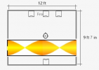
Not the most sophisticated drawing I've ever done for sure.

Subs are equidistant from me, one in front, one in back.

Unfortunately, REW SIM doesn't allow multiple crossover points between 2 subs. Front sub is crossed over at 160hz and the rear at 120hz. I had to work with what I have. I'm on a PC with active speakers so I don't have any fancy DACs or AVRs. I use my soundcard to control the main cross over and then split the sub connection. My main sub can handle up to a 200hz crossover (no need to go that high), but rear can only do 120. It's not a very good sub. Main sub is 12", rear is 6". Front/rear volume ratio is roughly 3:2 (no markings on either sub to know what it's actually at, and I don't have the tools to properly find out either).

My system is calibrated to 83dB summed. So I use the windows volume control so the ratios stay in tact. No delays, Both subs are in phase though set at 180 for some reason. Doesn't matter though results are the same. One sub is ported (main), the other sealed.

Took me a lot of tests to make it integrate well. Right and left sidewalls gave similar results but not as good. I preferred the sound of it behind me. No localization though which is nice. A bit more depth, if you ask me, having the higher cross over.

Room sim isn't very accurate because there are way too many variables at play that will determine the final outcome.

2 of the 4 walls are exterior, made of stucco, others are standard 5/8" sheetrock. Floor is raised 4" off the old floor (I suspect that was done because it's probably asbestos tiles), concrete slab, 4 windows probably leak sound, closet is 52" wide, 36" deep. Quite a bit of treatment.
 
Last edited:

neRok

Senior Member
Joined
Oct 7, 2022
Messages
304
Likes
175
Location
Australia
View attachment 306623

View attachment 306625

Not the most sophisticated drawing I've ever done for sure.

Subs are equidistant from me, one in front, one in back.
So roughly as follows?
ozzys room.png
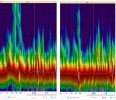
It reckons your subs individually are pretty flat at 125Hz (but certainly not at 120Hz), and you can see each sub/speakers contribution by hovering over it. Maybe it's not shown due to a discrepancy in dimensions, or maybe with relative absorption levels of the walls (all on min in my screenshot). But if you look at the speakers, they have "low SPL" at 125Hz (the L speaker is worse). So it's interesting to work out where that null came from. Was your first decay measurement speakers with 1 sub, and the next speakers with 2 sub? Have you done tests for each speaker and sub individually and seen which is having the problem?

Room sim isn't very accurate because there are way too many variables at play that will determine the final outcome.
Modes exist between parallel walls. Their impact depends upon the listening position relationship to the modes nodes, and as I just learned. the speakers relationship to it too, see Visualizing How Different Loudspeaker LF Directivity Patterns Couple to Room Modes. The mode is because of reflections, so sound absorption can reduce its impact. But it's still good to check REW Room Sim to see how those modes are affecting the measurements. You can see the reason for the big bump at 93Hz in the room sim for example.

93Hz is like that because you are sitting right in the peak of the room mode;
93hz.png
 

ozzy9832001

Senior Member
Joined
Feb 19, 2023
Messages
405
Likes
257
So roughly as follows?
View attachment 306633
It reckons your subs individually are pretty flat at 125Hz (but certainly not at 120Hz), and you can see each sub/speakers contribution by hovering over it. Maybe it's not shown due to a discrepancy in dimensions, or maybe with relative absorption levels of the walls (all on min in my screenshot). But if you look at the speakers, they have "low SPL" at 125Hz (the L speaker is worse). So it's interesting to work out where that null came from. Was your first decay measurement speakers with 1 sub, and the next speakers with 2 sub? Have you done tests for each speaker and sub individually and seen which is having the problem?


Modes exist between parallel walls. Their impact depends upon the listening position relationship to the modes nodes, and as I just learned. the speakers relationship to it too, see Visualizing How Different Loudspeaker LF Directivity Patterns Couple to Room Modes. The mode is because of reflections, so sound absorption can reduce its impact. But it's still good to check REW Room Sim to see how those modes are affecting the measurements. You can see the reason for the big bump at 93Hz in the room sim for example.

93Hz is like that because you are sitting right in the peak of the room mode;
View attachment 306635
Right, but what I'm saying is what it shows is nowhere near what it actually displays because differences in the room are too varied to be able to calculate it with a simple program. When real measurements are done, either RTA or single position. There never was a massive peak at 93hz. 140hz (ceiling mode) was the only real overblown peak. Everything else was mostly inline.

According to the simulation, the best position to be is on the short wall firing down the length of the room. In practice, that's a horrible location because of the closet in the corner and the 4 windows. If I flip my position around, the bass reacts significantly different when I have the speakers against the exterior wall. Concrete and drywall have way different absorption.

For the most part, 2 of the 3 standing waves are relatively easy to avoid through positioning alone. Getting all 3 is nearly impossible, so one has to either be dealt with or ignored completely. I felt the length was the easiest to deal with through a combo of higher crossover (which I happen to like) and multiple subwoofers. Localization I suppose could be an issue for sure, but I cannot hear it. Subwoofer size has some effect on how far it can be pushed before localization occurs.

Did it solve my problem? Yes. Is it ideal? Probably not. I'm sure there is some complicated physics involved that goes way over my head. All the data seems to indicate it had an extremely positive effect, and my ears agree with those findings. In all the literature I've read they say never use different subs, especially in size, but I had good luck with 2 different sizes even one is sealed the other is ported. But, it doesn't really surprise me, because the smaller sub is basically acting as a cancellation device.

I'd love to try 2 more subwoofers, but I feel having them all equidistant from the listening position is a key aspect often overlooked and I don't have the space on the sidewalls to put them. Thought maybe lining them up with the speakers wouldn't be a bad idea either.
 

neRok

Senior Member
Joined
Oct 7, 2022
Messages
304
Likes
175
Location
Australia
Right, but what I'm saying is what it shows is nowhere near what it actually displays because differences in the room are too varied to be able to calculate it with a simple program. When real measurements are done, either RTA or single position. There never was a massive peak at 93hz. 140hz (ceiling mode) was the only real overblown peak. Everything else was mostly inline.
The modes exist regardless, it's just math (but if you had so much room treatment, then it's possible they have no affect). And the screenshot I did before was with minimal absorption to exaggerate the problems. Increase the absorption a little and the SPL curve starts coming down quickly. Even with roughly corrected peak energy SPL, the modes still seem evident in your decay plots.
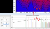
modes.png

I'm liking breaking everything down to see what each speaker is doing in room, and working out the problems that can be solved there. You might have found that your 125Hz problem could have been fixed with a narrow allpass on 1 speaker, but if you didn't break the problem down and try different fixes, you'll never know. The way you took your 2.1 measurement and added another subwoofer to fix 125Hz makes sense in that regard, because what you had was "balanced" to a null, and so your new sub is all new energy to hear.

But also, the room sim is showing 125Hz isn't a room length/width mode, so when I said "I'm sceptical of [multi-subs] ability to fix an issue related to a room length mode, which seem to be the worst problems", then it turns out your example isn't proving this point in favour of multi-sub anyway.

In all the literature I've read they say never use different subs, especially in size, but I had good luck with 2 different sizes even one is sealed the other is ported.
Different subs is potentially just making more problems because they have different timing properties that could cancel in some places, and add in others. This must not be happening to any major level in your room or it should be evident in the graph.

BTW, I was going to post more, but I realise the way you set your gains in your Room Sim screenshot is not correct. The gain in the sim is for relative gain adjustments "above anechoic". In my screenshot, if I tick "Show Anechoic Response", it simulates them all as 75dB at 0 gain. So whilst you might have gains set in your system elsewhere to get the SPL even between drivers and sub(s), you don't put this in the sim.
Edit: If you want "bass boost" (increased bass), then maybe what you did is correct.
 
Last edited:

dualazmak

Major Contributor
Forum Donor
Joined
Feb 29, 2020
Messages
2,854
Likes
3,063
Location
Ichihara City, Chiba Prefecture, Japan
Really interesting discussions are going on here especially on "room mode" of low Fq sound.

Judging and learning from your discussions, I now believe that the sound deadening spaces (or even rooms) behind our SP system as well as behind our listening position (behind our ears and head) would be critically important for excellent room acoustics as I shared/discussed here post #687 on my project thread.

You can find here the latest setup of my system as of August 3 2023 (including the best tuned Fq response at listening position).
 
Last edited:

ozzy9832001

Senior Member
Joined
Feb 19, 2023
Messages
405
Likes
257
I use a 5dB shelf from about 150hz to 40hz. I calibrated the system for 83dB, but rarely listen to it that high. I get the look if it's too loud. :0

I used 7/4 for the gains because the "ratio" of difference between the two. Neither is marked, so I have to guess based off how many "clicks" they give. 12" woofer is about 2dB per and the rear about 1.5 or thereabouts. I don't have the proper tools to actually measure it.

I tried the subs flanking me at the same distance as the speakers, but didn't like the effect it seemed to give (could localize), and whether at 180 or 0 polarity, it didn't look right at all on the spectrogram. Was all blotchy and broken. Kick drum lost a lot of it's umpf and was blending with the rest of the low bass. I think if I had 4 subs, I'd probably try the back 2 corners, behind me and centered between the speakers. I think that would work best for my room.

The other thing that's atypical is the way my AE5 handles the subwoofer out bass redirect. It doesn't look like it's really a slope, but rather a dB reduction. It's like -30 at crossover, almost like a shelf filter applied. Whereas the subwoofer out on my edifier 2850 is hard set at 100hz and drops at 36dB/octave. I just prefer it higher so I split the connection from my pc rather than from the speakers. Gives me more control as well.

At the end of the day, I'm just trying to get better sound. I just don't have access to all the fancy things that some do, so I make due with what I have.

My next step will be hooking up an old pair of Kanto YU4's and seeing if I can use them as rear speakers to cancel out some stuff. I just don't want to pay for DIRAC or soemthing else to do it. I hope to have some positive gains similar to your work with VBA.
 

OCA

Addicted to Fun and Learning
Forum Donor
Joined
Feb 2, 2020
Messages
679
Likes
499
Location
Germany
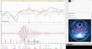
I found a new clipping test track better than Californication:

Album ArtistAlbumDisc#Track#TitleSource
Infected MushroomHead of NASA and the 2 Amish Boys
1​
1​
Bliss on MushroomsTidal

Around 5 minutes 30 second into the track, the rythm changes and it requires another 1.5dB headroom on top of Californication not to clip :)
 

neRok

Senior Member
Joined
Oct 7, 2022
Messages
304
Likes
175
Location
Australia
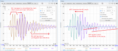
In case you all haven't seen, very helpful member beatelund posted before and after measurements of his system without EQ, with DL-BC, and with DL-ART.

Here is my take on what DL has done (also posted in that thread);
BC vs ART.png

So I think a lot of what I was attempting earlier in this thread was heading in the right direction.

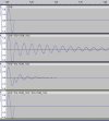
In another thread I also posted about some info which showed that room modes ring like a high-Q EQ filter, and so can be cancelled by applying the opposite. I just set about "testing" this for myself, and it is true!
EQ modes.jpg

That shows that the in room post-ringing from a played tone can be cancelled by also playing some post-ring in the opposite (the played post-ring will then also ring in the room, causing the on-going cancellation). In room is slightly different because of arrival times, so that's probably why DL-BC ends up delayed. DL-ART seems to then linearise that result.
 
  • Like
Reactions: OCA

Hayabusa

Addicted to Fun and Learning
Joined
Oct 12, 2019
Messages
837
Likes
583
Location
Abu Dhabi
In case you all haven't seen, very helpful member beatelund posted before and after measurements of his system without EQ, with DL-BC, and with DL-ART.

Here is my take on what DL has done (also posted in that thread);
View attachment 313973

So I think a lot of what I was attempting earlier in this thread was heading in the right direction.

In another thread I also posted about some info which showed that room modes ring like a high-Q EQ filter, and so can be cancelled by applying the opposite. I just set about "testing" this for myself, and it is true!
View attachment 313974

That shows that the in room post-ringing from a played tone can be cancelled by also playing some post-ring in the opposite (the played post-ring will then also ring in the room, causing the on-going cancellation). In room is slightly different because of arrival times, so that's probably why DL-BC ends up delayed. DL-ART seems to then linearise that result.
Nice! but generating that post ringing opposite seems to be non trivial.
 

neRok

Senior Member
Joined
Oct 7, 2022
Messages
304
Likes
175
Location
Australia
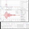
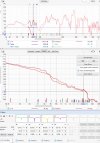
Here's my own measurement with a mode at 82.7Hz;
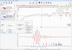
before.jpg

I have Filtered IR applied at 80Hz, so I can "EQ the IR". REW can pinpoint and auto-EQ the modes if you use no smoothing and narrow the match range, like I did here;
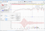
eq auto.jpg

REW found the mode at 82.7Hz for me. If I narrowed the range it would have only made a PK at 82.7, but here it added 2 nearby. I think these nearby filters are critical! I hadn't considered them earlier in the thread, because my mindset was more "fix 1 problem with 1 solution", but now I think they need to "stack" (overlap). So in that auto-EQ example, 82 PK is further improved by additional ringing from the nearby 73 and 89 filters. The auto-EQ has managed to "front load" more of the power, and reduce the severity of the ringing. I imagine this alone would be an improvement.

So now that I know to use nearby filters, I've been trying out some random combos, like this one;
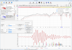
eq try1.jpg
I think I'm getting close to achieving the "consolidation" step. I just gotta work out the right combo of filters. I wonder if it needs more than IIR filters though...?

Edit: Thought I should look at the GD for the full response (unfiltered IR). I see GD peaks near the 3 frequencies I chose for the PK's above. Maybe the GD peaks are indicitive of the PK filters required? (frequency=center, Q=width, relative strength=height). If so, there might actually be a 4th PK required at ~94Hz.
GD.jpg
 
Last edited:

neRok

Senior Member
Joined
Oct 7, 2022
Messages
304
Likes
175
Location
Australia
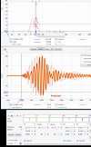
"Fixing the GD" looks promising;
EQ to GD.png
I went way to aggressive on the -dB, but the ringing improved massively, and the power moved forward. But whilst I was implementing those filters, I noticed the phase was becoming a nice smooth line;
EQ to GD - phase.jpg

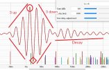
So I need to work out what my speakers "good SPL" is. I've seen many times now that a good IR is "3 up, 3 down", like this;
good wave.jpg
And a really good IR has the diamond peak as the strongest peak, stronger than the circled one.

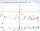
So I went to the spectrogram and identified some areas where there was no pre or post ringing problems.
(areas with ringing have energy outside the horizontal lines, and so potential good frequencies are indicated with vertical lines);
Identify good SPL.png

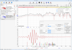
And then I used the "alignment tool > IR mode" to filter at those frequencies, and found that yes, some of those are "good";
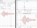
F_IR 44Hz.png F_IR 64Hz.png F_IR 110Hz.png F_IR 193Hz.png

So I think my bass is at ~95dB in that measurement. Now I will use that level as a reference for my filters.
 
Last edited:

ppataki

Major Contributor
Joined
Aug 7, 2019
Messages
1,249
Likes
1,417
Location
Budapest
I have realized that if I optimize to a pretty low dB target value (like 30dB below my highest peak) the resulting Wavelet graph will have significantly lower overall post-ringing (and more pre-ringing but definitely not audible)
I am not sure why that is but it definitely works
I usually use as many filters as possible to iron out the FR curve to as flat as possible (I guess that ironing-out has similar results to what you were showing above)
 

ppataki

Major Contributor
Joined
Aug 7, 2019
Messages
1,249
Likes
1,417
Location
Budapest
And another 'trick' if you use standard Dirac Live just measure in the main listening position only (just one measurement in total)
The resulting optimized FR curve will be totally flat (if you measure it back with REW)
For me that sounds much much better vs measuring in 9 or more positions (and yes I know that this method is strongly advised against also by Dirac.....but for me it sounds the best)
 

neRok

Senior Member
Joined
Oct 7, 2022
Messages
304
Likes
175
Location
Australia
And another 'trick' if you use standard Dirac Live just measure in the main listening position only (just one measurement in total)
The resulting optimized FR curve will be totally flat (if you measure it back with REW)
For me that sounds much much better vs measuring in 9 or more positions (and yes I know that this method is strongly advised against also by Dirac.....but for me it sounds the best)
For the bass region (below Schroeder frequency), that actually makes sense for a normal rectangular room with speakers on the short wall. That's because the length modes seem to dominate, and so moving left or right on a couch doesn't change the relationship to the length modes (nor the height modes). It would be a different story for people trying to do this with multiple rows of seating.

I am not sure why that is but it definitely works
It seems to be because room modes ring just like IIR filters, which seems like an epic coincidence!

Actually, maybe that's the answer: If every mode is going to ring like an IIR filter, then every mode needs an IIR filter. I'm going to duplicate the modes from this calc and see what happens.
 

ppataki

Major Contributor
Joined
Aug 7, 2019
Messages
1,249
Likes
1,417
Location
Budapest
I'm going to duplicate the modes from this calc and see what happens

What you can also try is to use linear phase filters - those have much less post-ringing but elevated pre-ringing, depending on the Q value - with lower Q values it shall still work fine.
What I do with my main system (see my signature) is that I use linear phase low-shelf as preEQ before Dirac. It produces audibly (!) less ringing vs using min phase low-shelf as preEQ. (PreEQ is needed since it is a sealed cabinet system hence low-end boosting is a must)
 

neRok

Senior Member
Joined
Oct 7, 2022
Messages
304
Likes
175
Location
Australia
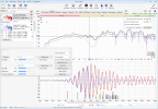
I've just played around with what I think is the FIR EQ method. I took a measure, copied it, and moved the copy near 0dB so that the peaks were at the +dB amount I wanted to EQ them negatively by. Then I realised I had to "fix" the SPL in place, so I tried both "response copy" and "min phase copy". Then with the copy I did inversion (1/A) and found 40 to 300Hz was working well for me, with ignore notches on. Then I would trim the convolution IR to where its step response seemed not so great (about -50 and +150ms).

The results are better than I expected. I've just been shuffling through my library and found a song that was nice and honky in my room without EQ applied. I looped the same ~10 seconds (timestamp in background) and measured with RTA. There was a peak in teh RTA matching a peak in the speaker response. Then I did the same with the FIR EQ applied, and that peak was way down. Here is a comparison of that with the filtered IR's at the problem frequency (~143Hz, which isn't a length mode, but close to the ceiling mode);
fir fix.jpg

The bulk of that IR looks much better. The power is forward in time, and the post-ringing reflections are much improved. There is some pre-ringing, but I'm not sure I can hear it in this circumstance (during a metal song). Maybe it can be heard in some situations, but I think the improvements in SPL and post-ringing are probably far more important. It does sound much better, as there is no honk, and some things sound better too. Maybe its a veiling thing too?

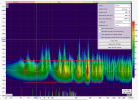
The spectrogram doesn't look particularly improved. especially considering how much better the IR looks;
spectro-fourier.jpg spectro-wavelet.jpg
The wavelet looks a smidge improved because it was yellow to ~70ms, now yellow to <50ms. Also there is a little less power after ~220ms.

So yer, this was better than I expected. Maybe a good idea is to fix problematic modes with manual IIR, and then FIR EQ what's left?
 

StabMe

New Member
Joined
Oct 28, 2021
Messages
2
Likes
1
I have read this while thread with interest. The idea that i can't get rid of is the following:

MSO tries to apply different settings to filters like peq, gain, delay, inversion to subs and mains and, using a sophisticated algo, searches for the flattest curve. What if one implements a similar code that optimizes for optimal RT60, Clarity or other metrics or a combination or those?

For example, i have a 4 channel setup (actually 4.4, but let's simplify for this example). Say i want flattest curve with least decay possible for all the speakers. We can program the software which will estimate how the metrics like rt60 react when inverted copies of one channel are delayed and played with that channel to 'catch' the reflections. Parameter ranges might be set within some sane constraints, like delays which should be an approximation of distances to the channel being corrected. PEQ might be added, lpf/hpf as well to limit correction up to certain frequency, maybe all pass filters to deal with phase rotation (or use linear phase). Let the software try different variations of those, apply the effects either via convolution or by some other way, derive and assess metrics. It might be much more CPU greedy than MSO. And things might get more complicated when you add subs.
 

tjcinnamon

Addicted to Fun and Learning
Joined
Mar 20, 2021
Messages
542
Likes
221
I have read this while thread with interest. The idea that i can't get rid of is the following:

MSO tries to apply different settings to filters like peq, gain, delay, inversion to subs and mains and, using a sophisticated algo, searches for the flattest curve. What if one implements a similar code that optimizes for optimal RT60, Clarity or other metrics or a combination or those?

For example, i have a 4 channel setup (actually 4.4, but let's simplify for this example). Say i want flattest curve with least decay possible for all the speakers. We can program the software which will estimate how the metrics like rt60 react when inverted copies of one channel are delayed and played with that channel to 'catch' the reflections. Parameter ranges might be set within some sane constraints, like delays which should be an approximation of distances to the channel being corrected. PEQ might be added, lpf/hpf as well to limit correction up to certain frequency, maybe all pass filters to deal with phase rotation (or use linear phase). Let the software try different variations of those, apply the effects either via convolution or by some other way, derive and assess metrics. It might be much more CPU greedy than MSO. And things might get more complicated when you add subs.
I have been thinking the same thing. I asked AndyC56 (the author of the software) on AVSForum and got “it’s not planned”.

If youre on AVS, go put in a plug for that idea!

I’d love to see that as well. I’d take “somewhat flat” with a lower decay over a “OCD flat”, any day of the week
 

OCA

Addicted to Fun and Learning
Forum Donor
Joined
Feb 2, 2020
Messages
679
Likes
499
Location
Germany
Easier said than done! Metrics like RT60, Clarity, etc. require time domain correction. It's very different to frequency domain correction MSO is optimizing. Not only these phase corrections will frequently cause unpredictable ringing effects but also because all the data is hidden behind Fast Fourier transformations, are mathematically very complex to generate.
 
Top Bottom