• Welcome to ASR. There are many reviews of audio hardware and expert members to help answer your questions. Click here to have your audio equipment measured for free!

REW, RTA and distortion settings

Thomas_A

Major Contributor
Forum Donor
Joined
Jun 20, 2019
Messages
4,316
Likes
3,270
Location
Sweden
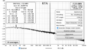
I was wondering how to set and interpret distortion in the RTA window of REW. Below is one measurement of a phono stage. Clearly one can see 50 Hz noise around -95 dB. However, the N figure is at -75 dB. How is the noise (N) calculated? Is this what should be expected? I can't really see how the graph and distortion figures compares to e.g. Amirs measurements here:


Distortion Muffsy 5 mV in.png
 
Zero dB on the graph is -21.41 dBFS (digital). If you amplify the signal to 0dBFS you also amplify the noise.
 
Zero dB on the graph is -21.41 dBFS (digital). If you amplify the signal to 0dBFS you also amplify the noise.
I had about 5 mV in and appox 0.4V out, and then to Cosmos at 4.5V sens. I will try changing sens.
 
Zero dB on the graph is -21.41 dBFS (digital). If you amplify the signal to 0dBFS you also amplify the noise.
Hm the background noise is amplified already in the graph. Looking at H2 it is at -107 dB, ie the number and graph fits well. The N figure is odd though. Trying to understand.
 
The top of the "grass" gives the noise level of each of the individual FFT frequency bins. Since there are a lot of frequency bins, to calculate the total noise, we need to sum them up. The difference between the top of the grass and the actual noise figure is often referred to as the FFT processing gain.

fft_gain.png

 
The top of the "grass" gives the noise level of each of the individual FFT frequency bins. Since there are a lot of frequency bins, to calculate the total noise, we need to sum them up. The difference between the top of the grass and the actual noise figure is often referred to as the FFT processing gain.

View attachment 305770
Thanks,

this was the info I needed. Is there standard settings for "FFT length" (size?) in REW that should be set when measuring?
 
Is there standard settings for "FFT length" (size?) in REW that should be set when measuring?
No, it depends on what level of distortion you want to see. The higher the FFT length the lower is the visual noise floor so even very low level peaks of distortion can be seen.

Afaik @amirm uses 32k in his dash board, with three averages. If you do the same with 4 averages in REW the results should look comparable.
 
No, it depends on what level of distortion you want to see. The higher the FFT length the lower is the visual noise floor so even very low level peaks of distortion can be seen.

Afaik @amirm uses 32k in his dash board, with three averages.
Yes I saw Amirs settings; and an AP-window that is an approximation to the Dolph-Chebyshev window. There are two such in REW named 150 and 200.
 
Noise is calculated by integrating the noise floor over your specified bandwidth (in your case 20-20K). When REW reports a value in dB (not dBFS) it is in reference to the level of fundamental. So your unweighted, 20-20K noise floor has a voltage that is -75 dB below your fundamental which is at a level of -21 dBFS. Important to note that the noise floor is a combination of the ADC noise floor and the DUT noise floor.

FFT length only changes the visual appearance of the noise floor, using a longer FFT length should have no impact on the REW reported noise. As mentioned by others the advantage of using a longer FFT length is to visually lower the noise floor so you can see distortion spikes that would otherwise be buried.

I had about 5 mV in and appox 0.4V out, and then to Cosmos at 4.5V sens. I will try changing sens.

Ideally you would set the sensitivity such that you can achieve as close to 0 dBFS input on the ADC as possible without clipping. Let's say your ADC has 120 dB dynamic range, if your signal level is -21 dBFS you will never measure a noise level better than 120 - 21 = 99 dB. Although in your specific case it doesn't look like your measurement is being limited by the ADC even at a 4.5 V input setting.

Michael
 
Last edited:
Ideally you would use as low of sensitivity as possible without clipping the ADC input. Let's say your ADC has 120 dB dynamic range, if your signal level is -21 dBFS you will never measure a noise level better than 100 - 21 = 79 dB. Using a lower sensitivity and getting the fundamental close to 0 dBFS will give you the best possible noise floor measurement.
Just as small correction:
"as low a sensitivity as possible" -> "as high a sensitivity as possible"
"Using a lower sensitivity" -> "using a higher sensitivity"
 
Just as small correction:
"as low a sensitivity as possible" -> "as high a sensitivity as possible"
"Using a lower sensitivity" -> "using a higher sensitivity"

Haha, was just thinking that as I re-read. It is definitely a higher sensitivity if you have a lower maximum input level.

Michael
 
Noise is calculated by integrating the noise floor over your specified bandwidth (in your case 20-20K). When REW reports a value in dB (not dBFS) it is in reference to the level of fundamental. So your unweighted, 20-20K noise floor has a voltage that is -75 dB below your fundamental which is at a level of -21 dBFS. Important to note that the noise floor is a combination of the ADC noise floor and the DUT noise floor.

FFT length only changes the visual appearance of the noise floor, using a longer FFT length should have no impact on the REW reported noise. As mentioned by others the advantage of using a longer FFT length is to visually lower the noise floor so you can see distortion spikes that would otherwise be buried.


Ideally you would set the sensitivity such that you can achieve as close to 0 dBFS input on the ADC as possible without clipping. Let's say your ADC has 120 dB dynamic range, if your signal level is -21 dBFS you will never measure a noise level better than 120 - 21 = 99 dB. Although in your specific case it doesn't look like your measurement is being limited by the ADC even at a 4.5 V input setting.

Michael
Thanks, and yes it is not easy to achieve. I used two passive -20 dB attenuators in a row getting a better "slope" (RIAA), indicating that noise is also coming from ADCs etc. So THD+N is probably slightly better than -76 dB here at circa 5 mV in. Manufacturer says -79 dB.
Distortion Muffsy 5 mV in 2.png
 

Attachments

  • distortion 1 khz muffsy.png
    distortion 1 khz muffsy.png
    62.3 KB · Views: 87
Another question regarding REW. I tried to measure the device (a phono pre) using sweep and I get strange results. In SPL windows I get wavy pattern and truncated response from 200 Hz. This is with an added RIAA calibration curve, but it does not matter if its there or not. I still starts at 200 Hz and has a wavy pattern.

Measurement SPL.png

If I instead look at the distortion menu, I get the whole response (which is not wavy) from 10 Hz and up, but then without a calibration curve applied. So it looks like the RIAA.
Mesurement dist.png

Why is this happening? Why cannot I get the whole response?
 
Stupid me. Window size.
 
Back
Top Bottom