Try playing around with the optimizer tab if you havent already, very helpful for setting target slopes if you cant identify a LR24 or BW12 slope just by looking at a SPL graph (like reading music a bit aint it?)
-
Welcome to ASR. There are many reviews of audio hardware and expert members to help answer your questions. Click here to have your audio equipment measured for free!
You are using an out of date browser. It may not display this or other websites correctly.
You should upgrade or use an alternative browser.
You should upgrade or use an alternative browser.
Post Directiva r1 Active Crossovers here
- Thread starter RickS
- Start date
From an "design" perspective, i like the approach described in the Grimmaudio LS1 paper, and their preference for LR24 filters:
I would like to request your help to identify the potential problems with this crossover, and what data indicates those potential problems.
Also, if possible, identify what could be done to improve the end result.
The grimm audio approach is a sensible one for creating an active speaker crossover.
What they do is equalize both drivers to be flat on the reference axis for 1 to 2 octaves either side of the crossover using PEQ.
Then they use digital delay to time align the drivers and slap a 4th order LR electrical filter on it.
Because the drivers are flat either side and time aligned the acoustic slope of the crossover matches the electrical one very closely. The combined result remains flat.
This will give a phase match at crossover. You have used different frequencies for the filters and the relative phase of the drivers has moved apart.
Following the above will get rid of the lump in the response centred at 1k which will sound odd.
It looks good to me. I'd compare the distortion and waterfalls for all XOs. Ears should ultimately decide.I would like to request your help to identify the potential problems with this crossover, and what data indicates those potential problems.
Also, if possible, identify what could be done to improve the end result.
Is the DI more important than the ceiling and floor bounce? Is the on-axis power less important than the DI? It is neat to see the tradeoff but I always wonder what can be heard. I think all the XO's that folks made cover the bases so it will be neat to see what is preferred.
I would nudge toward having 3khz -14db down or more. Did you see the waterfall for the woofer? That shit can make things like applause sound weird. I'd like to have decay issues just as low as distortion issues- like -30db or more.
I wish you could change out what is in the six-pack of images.That would also remove the crazy impedance total (which isn't actually seen by any amplifier) and any confusion.
Also, I believe, same as the miniDSP technique over on their websites application notes. Very simple for someone to get set up, even with just a UMIKThe grimm audio approach is a sensible one for creating an active speaker crossover.
minidsp have created many application notes to explain various techniques for use with their products which are useful in general but the ideas behind them belong to someone else. Grimm audio were in no way the first either. Linkwitz himself did it this way for all his speakers for much longer analogue and digital.Also, I believe, same as the miniDSP technique over on their websites application notes. Very simple for someone to get set up, even with just a UMIK
I see, it makes sense ... i've read the grimm audio paper a long time ago, and i forgot the details ...You have used different frequencies for the filters and the relative phase of the drivers has moved apart.
So, based on your clarification regarding the Grimm Audio approach, these are the steps i took:
0 - Import the Phi0Theta0 driver files to REW
1 - Use REW to equalize both drivers to be flat
For the Purify, i used a range between 500 and 3500, and a max of 5 filters:

For the SEAS, i used a range between 1000 and 20.000 and a max of 5 filters:

2 - Insert the filters for each driver, bellow the Purify corrected response:

3 - Add the LR24 filters for Purify and Seas, using a symmetric 3000Hz crossover Point
4 - Added the Power amplifier, and tweaked gain and delay to achieve the best Preference Rating:

Results


This gave me a final Preference rating of 7.085.
My main question here, is how to decide the best Crossover Point: i basically tried several XO points between 2000 and 3000, and 3000 was the one that allowed me to achieve the best Preference rating result.
Using the measures available, is there a "scientific" approach to select the best XO point?
What you need to do now is to look at the off axis curves the listening window, pir and soundpower and see what effect the different crossover points have. Check to see if the 6 to 7k peak of the woofer becomes visible off axis, in an active crossover I would take it out anyway. Then you can look at optimizing the listening window as making the on axis flattest does not always give the best overall response. Do not concentrate on the score so much certainly to decimal places. I have not looked at these measurements in detail to offer any more specific advice.
When doing active and correcting the driver response, should we use all the DSP available filters to make the response as perfect as possible, or is preferable to limit the number of filters? Is there any drawback in using 10 filters instead of 5, given that using 10 filters will allow to achieve a flatter driver response?

There is no real penalty with a DSP in using more filters to flatten the drivers. What you need to be careful of is trying to use high q filters, correcting every tiny thing or making one axis super flat to the detriment of other off axis angles.When doing active and correcting the driver response, should we use all the DSP available filters to make the response as perfect as possible, or is preferable to limit the number of filters? Is there any drawback in using 10 filters instead of 5, given that using 10 filters will allow to achieve a flatter driver response?
Can you layer this crossover over the one Amir measured?I see, it makes sense ... i've read the grimm audio paper a long time ago, and i forgot the details ...
So, based on your clarification regarding the Grimm Audio approach, these are the steps i took:
0 - Import the Phi0Theta0 driver files to REW
1 - Use REW to equalize both drivers to be flat
For the Purify, i used a range between 500 and 3500, and a max of 5 filters:
For the SEAS, i used a range between 1000 and 20.000 and a max of 5 filters:
2 - Insert the filters for each driver, bellow the Purify corrected response:
3 - Add the LR24 filters for Purify and Seas, using a symmetric 3000Hz crossover Point
4 - Added the Power amplifier, and tweaked gain and delay to achieve the best Preference Rating:
Results
This gave me a final Preference rating of 7.085.
My main question here, is how to decide the best Crossover Point: i basically tried several XO points between 2000 and 3000, and 3000 was the one that allowed me to achieve the best Preference rating result.
Using the measures available, is there a "scientific" approach to select the best XO point?
Can you layer this crossover over the one Amir measured?
I hope i've done it correctly
")

I hope i've done it correctly
so it's basically the same on axis ?
how does PIR looks?

Predicted in-room response. I'm nothing close to an expert btw, it's just that you need to keep in mind that the original project doesn't completely match reality, Amir's measurements in the review do.
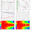
This is @morpheusX design using the Grimm X-over methodology - the phase coherence looks really good, however there's a DI error due to the high crossover point and the woofer beaming (I think) - albeit minor! I'd definitely give this XO a go!
EDIT - actually that 1.6khz DI error looks more like a measurement artifact from behind the speaker - I wouldn't even worry about it. This sure looks like the way to go for XO
Last edited:
... however there's a DI error due to the high crossover point and the woofer beaming (I think) - albeit minor! ...
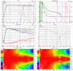
Looking at the woofer response from 0º to 50º, it seems indeed that the XO is too high:

I tried using a 2.5K XO point, but phase didn't align so well, and in order to have it aligned, i had to set a delay on the tweeter up to 200us, which would lower the rating:

I don't know how to interpreter the Phase result between the 2.5K and the 3K crossover; it seems very different than the one for 3K, although i don't even know which one is better or worse
I've been looking for some documentation on how to interpreter the measurements to be able to find the best XO point, but haven't been able to find anything.
Jeff Bagby has a paper on JeffB’s Thoughts on Passive Crossover Design, but it doesn't cover how to choose the best XO points.
(he also does state a preference for LR4 crossovers for DIY Home speakers).
That is the vertical response of the woofer, the horizontal looks much better. It makes more sense initially to concentrate on the horizontal and then see how that has affected the vertical.Looking at the woofer response from 0º to 50º, it seems indeed that the XO is too high:
I don't know how to interpreter the Phase result between the 2.5K and the 3K crossover; it seems very different than the one for 3K, although i don't even know which one is better or worse
I've been looking for some documentation on how to interpreter the measurements to be able to find the best XO point, but haven't been able to find anything.
The phase does not have to overlay and track it depends on the intent of the filters, some crossovers introduce deliberate phase mismatch to achieve the overall desired response.
In general the crossover point is chosen to avoid the woofer breakup getting in or the tweeter being overextended. The Purifi woofer has very benign rolloff and breakup and the tweeter can be used fairly low with the waveguide so there is a range of options for reasonable crossover points. There is no paint by numbers approach here. Practice, experience and listening to the differences will help guide you.
One rule of thumb that can get you in the ball park with a woofer and waveguided tweeter is to look at the 60 degree off axis curve and see where both are at about -3.5dB.
The benefit of Vituix is that you can simultaneously look at how the on axis EQ or crossover affected all the off axis curves and iterate until you get what you want.
The 140 and 150 degree responses of the woofer also show why there is that directivity dip due to soundpower increase around those frequencies.
I got curious enough to download the crossover files and have a play with them. The original crossover scheme seems really quite good to me and does a nice job of balancing the two drivers. The Purifi and DXT are not an ideal directivity match. I made a few minor tweaks and it looks a bit flatter. I have changed the reference axis to 20 degrees horizontal as the DXT is very well behaved there. The original crossover also looks better to me if the reference axis was 20 degrees. I also made a different style with 8th order Linear phase Linkwitz Riley filters and a fair bit of EQ. It produces a power response dip and corresponding DI bump which I think is better than a DI dip and power response peak but the high order filters minimize the vertical narrowing around crossover. Vituix project attached that can be placed in the folder with the original files. R1 is the as measured crossover, R2 is the linear phase and R3 the tweaked stock crossover.
GIF Comparison R1 to R3

GIF Comparison R1 to R3
Attachments

Currently working on my take on "Directiva" and here are some early captures. These are not final, I am still playing with the crossover, but what I have is promising and sounds nice too, just mono testing. I used the REW EQ-drivers-flat-on-axis-past-XO-points method, as discussed earlier. Started with 3k but will likely lower to 2.4-2.5k as my woofer looks like it has some funny behavior around 3-4khz off axis making for a bump in the sound power there.
My version is a ported floorstander with an F3 of ~35hz. I'm experimenting with wavelength traps with the port plumbing within the base of the floorstander cabinet, as I discussed in the directiva thread, to significantly reduce port resonances. Again, its still early days with the final port tune. Measurement equipment is a combination of EMM6 mic, UMIK-1, 4.5ms window stitching to near field LF measurements. I haven't had the time to do full turntable measurements, hopefully this weekend. It should be noted the EQ's I arrived at were way off rick/ctrl/amir's, using those EQ's (from this thread) gave me a wide smile curve. The differences between driver responses is worth paying attention to!


As I said, some interesting off axis stuff happening and some things I suspect I wont be able to capture with the current 4.5ms window but its not terrible. Open to criticisms. To the music very soon, I hope~!
My version is a ported floorstander with an F3 of ~35hz. I'm experimenting with wavelength traps with the port plumbing within the base of the floorstander cabinet, as I discussed in the directiva thread, to significantly reduce port resonances. Again, its still early days with the final port tune. Measurement equipment is a combination of EMM6 mic, UMIK-1, 4.5ms window stitching to near field LF measurements. I haven't had the time to do full turntable measurements, hopefully this weekend. It should be noted the EQ's I arrived at were way off rick/ctrl/amir's, using those EQ's (from this thread) gave me a wide smile curve. The differences between driver responses is worth paying attention to!
As I said, some interesting off axis stuff happening and some things I suspect I wont be able to capture with the current 4.5ms window but its not terrible. Open to criticisms. To the music very soon, I hope~!
Similar threads
- Replies
- 2
- Views
- 763