• WANTED: Happy members who like to discuss audio and other topics related to our interest. Desire to learn and share knowledge of science required. There are many reviews of audio hardware and expert members to help answer your questions. Click here to have your audio equipment measured for free!

old, crappy tape deck advice...

OP
R

rdenney

Major Contributor
Forum Donor
Joined
Dec 30, 2020
Messages
2,271
Likes
3,975
The 4300 is turning into quite a nice deck. It has certainly needed work.

First, I had to clean and lubricate the pinch rolled mechanism, which made the transport snappy. I replaced both belts, and installed a new pinch roller.

The right channel was cutting out, and that turned out to be a broken ground wire connecting the ground plane between the equalizer amp and the line amp. Then, the right channel of the headphone amp was scratchy and intermittent, and replacing caps in that section didn’t fix it. But replacing the main transistor (from a donor board) in the headphone amp resolved the issue.

Now, the meters are uncalibrated and the channel balance is off. I have a replica of a Teac calibration tape coming from Germany, and will use that to check the azimuth, adjust playback EQ, set the bias levels, and reset the line amp and meter levels.

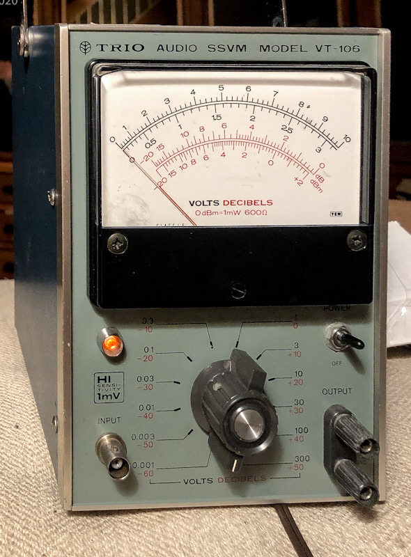
My test equipment is age-appropriate: a Tektronix T932A scope, a Simpson meter, and a new-to-me Trio solid-state VTVM, which will measure AC voltages down to -80 dBm (precision to 2% of .001V). I could do the same thing with the scope, but peaking an analog meter is a lot easier.

Living-room-lab.JPEG


Trio-uV-meter.JPEG


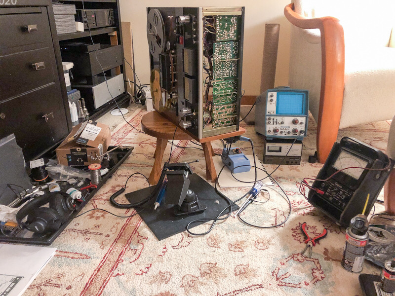
I performed a test recording from a CD on Capture 914, a cheap but new reel of tape. Quality was a bit lo-fi but without apparent electronic fault, so it’s a matter of proper EQ adjustment and level calibration. Heads are in very good condition.

Yes, it’s stupid to put effort like this into a device with noise levels abundantly high enough to measure with that Trio microvolt meter, but I just can’t help it.

Final report when I get it calibrated.

Rick “calibration tape floating across the pond on a slow boat” Denney
 

restorer-john

Grand Contributor
Joined
Mar 1, 2018
Messages
12,727
Likes
38,926
Location
Gold Coast, Queensland, Australia
Late to the thread, and I am so sorry for your loss.

Definitely go for a three motor unit, all the belts, back tension and clutching/idler problems are simply not present. The DD capstan motor units and reel outer rotor motor (Akai) decks are fabulous too. (Big GX units).

My favourite Akai GX-625. Once you've dealt with all the noisy Hitachi transistors, it's pretty much bulletproof.

(not my pic- internet pic)
1623639348500.png


Auto reverse can be trouble, as you have more heads, twice as many capstans and pinch rollers and tension issues to deal with.
 
OP
R

rdenney

Major Contributor
Forum Donor
Joined
Dec 30, 2020
Messages
2,271
Likes
3,975
The Teac 4300 has auto-reverse, but uses a single capstan. There is an additional playback head to calibrate.

I looked at the Akai models with the ferrite heads (like the one you noted), but anything with 10” reel capacity increases the price substantially, and the AC hysteresis capstan motor on the Teac easily survives being stalled, which is a reported challenge for some of the direct-drive DC motors used in later decks. The A-series Teacs are pretty hard to beat for hobbyist repairability.

Rick “still able to buy consumable parts directly from Teac” Denney
 
OP
R

rdenney

Major Contributor
Forum Donor
Joined
Dec 30, 2020
Messages
2,271
Likes
3,975
Update: I've set all the levels using the calibration tape, and the frequency response is +/- 1dB from 32 Hz (the lowest tone on the tape) to 16 KHz (the highest tone) at 7-1/2 ips. Speed is close enough. There is some wow, wiggling around 0.5 dB, and I need to figure out in relation to what rotating device, but it's probably the belt and I may try a different one. It doesn't sound like frequency wow, but rather level. That's hard to tell, though, and I need to record output to the computer and study it. I don't see wavelength changing on the scope, but it may be too small a change to see. The frequency counter doesn't notice it at all, but then it samples too slowly. Hiss is definitely audible--maybe 50 dB down from 0 VU, but I've set 0 VU to correspond to -8 dBm for tape with flux of 185 nWb/m, which does not explore the capabilities of better tapes.

Playback is in the category of "good enough" for the project at hand.

The record equalization is a bit wacky, barely within specs but not ideal. If I declare 40 Hz to be -3 dB wrt the target VU, the top octave will range from +2 to +4. Frequency response does not drop off until 20 KHz at 7-1/2 ips at either -28 dBm (-20 VU) or 0 VU, though the distortion at 20 KHz is substantial (maybe -10 dB). I can record signals down to 20 Hz with little loss of record level. The treble response emphasizes noise, which sounds at least 10 dB louder than the background hiss on the calibration tape. Any leakage of the bias oscillator (100 KHz) is below -40 dB, as specified. The bias EQ adjustment isn't enough to deal with this, but the tape (Capture 914) isn't perhaps the best for this exercise, so I'll try again. More to play with there before I put the covers back on.

Rick "learning as I go" Denney
 

antennaguru

Senior Member
Joined
Jun 16, 2021
Messages
391
Likes
416
Location
USA
Often it's the pinch roller that causes the wow/flutter. When you play the reference tape the test tone(s) should be read rock solid on the display of a good stable frequency counter using a fast gate time.

Condolences for your loss.
 
Last edited:

MakeMineVinyl

Major Contributor
Joined
Jun 5, 2020
Messages
3,558
Likes
5,875
Location
Santa Fe, NM
Update: I've set all the levels using the calibration tape, and the frequency response is +/- 1dB from 32 Hz (the lowest tone on the tape) to 16 KHz (the highest tone) at 7-1/2 ips. Speed is close enough. There is some wow, wiggling around 0.5 dB, and I need to figure out in relation to what rotating device, but it's probably the belt and I may try a different one. It doesn't sound like frequency wow, but rather level. That's hard to tell, though, and I need to record output to the computer and study it. I don't see wavelength changing on the scope, but it may be too small a change to see. The frequency counter doesn't notice it at all, but then it samples too slowly. Hiss is definitely audible--maybe 50 dB down from 0 VU, but I've set 0 VU to correspond to -8 dBm for tape with flux of 185 nWb/m, which does not explore the capabilities of better tapes.

Playback is in the category of "good enough" for the project at hand.

The record equalization is a bit wacky, barely within specs but not ideal. If I declare 40 Hz to be -3 dB wrt the target VU, the top octave will range from +2 to +4. Frequency response does not drop off until 20 KHz at 7-1/2 ips at either -28 dBm (-20 VU) or 0 VU, though the distortion at 20 KHz is substantial (maybe -10 dB). I can record signals down to 20 Hz with little loss of record level. The treble response emphasizes noise, which sounds at least 10 dB louder than the background hiss on the calibration tape. Any leakage of the bias oscillator (100 KHz) is below -40 dB, as specified. The bias EQ adjustment isn't enough to deal with this, but the tape (Capture 914) isn't perhaps the best for this exercise, so I'll try again. More to play with there before I put the covers back on.

Rick "learning as I go" Denney
Level fluctuations are usually not a function of a mechanical fault like wow or flutter. Some tapes have better stability than others; I've found RTM SM-468 to be excellent in all regards. Fluctuations are worse the higher the frequency; 400Hz should be pretty steady with 1kHz slightly less so. Its pointless to expect the level to not fluctuate at higher frequencies, even at 15 ips.

You should really set the 1kHz playback level to "0" db when using a 185nWb/m tape. This should be done at 7 1/2 and 15 ips. Setting it lower is absolutely going to cause increased hiss.

Aligning at 7 1/2 ips is a compromise. The alignment should be done at -10 db at least and the bias might need to be adjusted to get the flattest response, irrespective of the record EQ adjustment. At 15 ips, full level alignment is possible across the full audio spectrum.
 

restorer-john

Grand Contributor
Joined
Mar 1, 2018
Messages
12,727
Likes
38,926
Location
Gold Coast, Queensland, Australia
Level fluctuations are usually not a function of a mechanical fault like wow or flutter. Some tapes have better stability than others; I've found RTM SM-468 to be excellent in all regards. Fluctuations are worse the higher the frequency; 400Hz should be pretty steady with 1kHz slightly less so. Its pointless to expect the level to not fluctuate at higher frequencies, even at 15 ips.

You should really set the 1kHz playback level to "0" db when using a 185nWb/m tape. This should be done at 7 1/2 and 15 ips. Setting it lower is absolutely going to cause increased hiss.

Aligning at 7 1/2 ips is a compromise. The alignment should be done at -10 db at least and the bias might need to be adjusted to get the flattest response, irrespective of the record EQ adjustment. At 15 ips, full level alignment is possible across the full audio spectrum.

The Teac 4300 only does 3.75 and 7.5 ips.
 
OP
R

rdenney

Major Contributor
Forum Donor
Joined
Dec 30, 2020
Messages
2,271
Likes
3,975
Level fluctuations are usually not a function of a mechanical fault like wow or flutter. Some tapes have better stability than others; I've found RTM SM-468 to be excellent in all regards. Fluctuations are worse the higher the frequency; 400Hz should be pretty steady with 1kHz slightly less so. Its pointless to expect the level to not fluctuate at higher frequencies, even at 15 ips.

You should really set the 1kHz playback level to "0" db when using a 185nWb/m tape. This should be done at 7 1/2 and 15 ips. Setting it lower is absolutely going to cause increased hiss.

Aligning at 7 1/2 ips is a compromise. The alignment should be done at -10 db at least and the bias might need to be adjusted to get the flattest response, irrespective of the record EQ adjustment. At 15 ips, full level alignment is possible across the full audio spectrum.

My deck is a nice consumer deck, which means 7" reels and 7-1/2 ips top speed.

I set the levels according to the service manual to start with. At 400 Hz, the line input is at -8 dBm, and the playback level is adjusted to -8 dBm (with respect to 600 ohms--0 dBm is 0.775V RMS), and the meters are set at 0 VU for that level. That's the "standard level" for the line-stage preamp--it's about at 2 O'Clock. If the tape is recorded to +6 VU, the output voltage should be 616 mv--a typical full source output before the days of CD players. But it can be cranked up another 8 dB or so to get the output pot to the highest setting (with what distortion effects I don't know). I'm using the SSVM pictured above to measure the levels--it's quite precise. And it matches my scope. Added to the kit is other unearthed old test equipment--my Tek frequency counter and my Tek signal generator, which I'm using for setting record levels because it's easy to measure its voltage output with precision.

I have loaded the line outputs as specified in the service manual with 10K resistors.

According to the manual, the bias is adjusted for peak output at 7.5 KHz, less half a dB, with the level at -28 dBm (-20 VU). It was during that exercise that I noticed the needle swaying back and forth about a dB total.

I don't much care about frequency response above about 12 KHz, but it would be nice if the record level at 1 KHz was pretty close to 8 or 10 KHz. The EQ is adjusted using variable inductors in tank circuits, but they have really very little effect. I need to play with it more--I was tired by the time I got to that and unwilling to really explore it at different levels and at more frequencies. But I did do a frequency sweep--I just didn't take notes as to where it really started to jump up. I suspect that if I record at peaks up to +5 or 6 VU, which seems to be within the capability of even the cheap tape I was using, I'll get less noise, assuming I'm not getting a big hump at 8 or 10 KHz.

Recorded music sounds pretty darn good, and that's using the less-than-stellar 8-ohm headphone amp in the thing with K371 headphones. Not as good as straight off the CD or out of the DAC, of course.

Also, I have some Maxell UD tape around here somewhere that's more like what I would record on if I decided to record something. I need to find a reel in my stash and set the bias for that.

Rick "having to do these projects late a night" Denney
 
OP
R

rdenney

Major Contributor
Forum Donor
Joined
Dec 30, 2020
Messages
2,271
Likes
3,975
Often it's the pinch roller that causes the wow/flutter. When you play the reference tape the test tone(s) should be read rock solid on the display of a good stable frequency counter using a fast gate time.

Condolences for your loss.
The calibration tape is solid, but there is a little bit of a phase shift that varies in cycle with the wow visible at high frequencies in one channel. The pinch roller is new from Teac.

Rick "who'll have the old roller redone by Terry's Rollers when he is back in the saddle" Denney
 

restorer-john

Grand Contributor
Joined
Mar 1, 2018
Messages
12,727
Likes
38,926
Location
Gold Coast, Queensland, Australia
but there is a little bit of a phase shift that varies in cycle with the wow visible at high frequencies in one channel.

Maybe your tape is skewing. Is the pinch roller perfectly flat or does it have a slightly raised (convex) surface?

Wow is low frequency and slow variation. You cannot have HF wow. 0.3Hz-6Hz and flutter is 6-200Hz.

Put the recording through an FFT, you can then isolate what the issue may be. Capstan rotation, pinch roller bearing, guide rollers, supply/takeup motor, head woodles/scrape etc.

If the fixed guides are worn, you may be able to rotate them to expose a new surface or polish them in situ.
 
OP
R

rdenney

Major Contributor
Forum Donor
Joined
Dec 30, 2020
Messages
2,271
Likes
3,975
Maybe your tape is skewing. Is the pinch roller perfectly flat or does it have a slightly raised (convex) surface?

Wow is low frequency and slow variation. You cannot have HF wow. 0.3Hz-6Hz and flutter is 6-200Hz.

Put the recording through an FFT, you can then isolate what the issue may be. Capstan rotation, pinch roller bearing, guide rollers, supply/takeup motor, head woodles/scrape etc.

If the fixed guides are worn, you may be able to rotate them to expose a new surface or polish them in situ.
It doesn't appear to be, and I even used my finger as a very light backing pad momentarily just to see if the effect changed. It didn't. But I do think it is related to the forward playback head, and not to the reverse playback head, from testing I did a couple of weeks ago. That would isolate it to the head, it seems to me.

The cycle of the effect is definitely down in the 1-Hz range. But the effect itself is mostly seen (on the scope) and heard at high frequencies.

Rick "much more to be done" Denney
 

antennaguru

Senior Member
Joined
Jun 16, 2021
Messages
391
Likes
416
Location
USA
Great that you replaced the pinch roller, and have plans for an even better one!

In that case it sounds like you probably need to make a slight Azimuth adjustment to the playback head to bring both channels in phase with each other. That's really easy to do! You'll need to use your 2 Channel scope set up for X + Y while monitoring both channels (tape outputs) while playing the test tone(s) on the test tape. You don't need to use scope probes and can simpy use two cables with an RCA on one end for the deck, and a BNC (or RCA to BNC adapter) on the other end for the scope. This will give you a Lissajous pattern on the screen. Basically it will look like a circle to an ellipse, with a wobble, and you would like it to look like a straight line at 45 degrees/diagonal on the screen. Refer to the TEAC Service Manual for the screw on the head stack for the playback head Azimuth, as that's the one you need to tweak, and there are many other screws there. Then put some nail polish or Glyptol on it to hold the setting after it has been tweaked. You will now have a perfect playback head Azimuth.

If you have gone this far and want to go even further you can then record a test tone from a function generator onto a blank tape, set your VU meters to 0 for the record level with the line input knob(s) while monitoring the source (function generator connected to tape inputs), and then flip the source/tape switch from source to tape and you will be seeing at how the record head alignment looks through your now perfect playback head alignment. If desired you can tweak the record head Azimuth screw like you did with the playback head. Usually it's no more than a fraction of a turn to tweak these...
 

restorer-john

Grand Contributor
Joined
Mar 1, 2018
Messages
12,727
Likes
38,926
Location
Gold Coast, Queensland, Australia
It doesn't appear to be, and I even used my finger as a very light backing pad momentarily just to see if the effect changed. It didn't. But I do think it is related to the forward playback head, and not to the reverse playback head, from testing I did a couple of weeks ago. That would isolate it to the head, it seems to me.

The cycle of the effect is definitely down in the 1-Hz range. But the effect itself is mostly seen (on the scope) and heard at high frequencies.

Rick "much more to be done" Denney

Post a recording of the sound?

Great that you replaced the pinch roller, and have plans for an even better one!

In that case it sounds like you probably need to make a slight Azimuth adjustment to the playback head to bring both channels in phase with each other. That's really easy to do! You'll need to use your 2 Channel scope set up for X + Y while monitoring both channels (tape outputs) while playing the test tone(s) on the test tape. You don't need to use scope probes and can simpy use two cables with an RCA on one end for the deck, and a BNC (or RCA to BNC adapter) on the other end for the scope. This will give you a Lissajous pattern on the screen. Basically it will look like a circle to an ellipse, with a wobble, and you would like it to look like a straight line at 45 degrees/diagonal on the screen. Refer to the TEAC Service Manual for the screw on the head stack for the playback head Azimuth, as that's the one you need to tweak, and there are many other screws there. Then put some nail polish or Glyptol on it to hold the setting after it has been tweaked. You will now have a perfect playback head Azimuth.

If you have gone this far and want to go even further you can then record a test tone from a function generator onto a blank tape, set your VU meters to 0 for the record level with the line input knob(s) while monitoring the source (function generator connected to tape inputs), and then flip the source/tape switch from source to tape and you will be seeing at how the record head alignment looks through your now perfect playback head alignment. If desired you can tweak the record head Azimuth screw like you did with the playback head. Usually it's no more than a fraction of a turn to tweak these...

On an autoreverse deck, tweaking a record head for one direction without taking into account the reverse direction playback head too (it's a balancing act on a deck that plays back both sides but only records in one direction (ie single erase head)) will cause no end of trouble.
 
OP
R

rdenney

Major Contributor
Forum Donor
Joined
Dec 30, 2020
Messages
2,271
Likes
3,975
Great that you replaced the pinch roller, and have plans for an even better one!

In that case it sounds like you probably need to make a slight Azimuth adjustment to the playback head to bring both channels in phase with each other. That's really easy to do! You'll need to use your 2 Channel scope set up for X + Y while monitoring both channels (tape outputs) while playing the test tone(s) on the test tape. You don't need to use scope probes and can simpy use two cables with an RCA on one end for the deck, and a BNC (or RCA to BNC adapter) on the other end for the scope. This will give you a Lissajous pattern on the screen. Basically it will look like a circle to an ellipse, with a wobble, and you would like it to look like a straight line at 45 degrees/diagonal on the screen. Refer to the TEAC Service Manual for the screw on the head stack for the playback head Azimuth, as that's the one you need to tweak, and there are many other screws there. Then put some nail polish or Glyptol on it to hold the setting after it has been tweaked. You will now have a perfect playback head Azimuth.

If you have gone this far and want to go even further you can then record a test tone from a function generator onto a blank tape, set your VU meters to 0 for the record level with the line input knob(s) while monitoring the source (function generator connected to tape inputs), and then flip the source/tape switch from source to tape and you will be seeing at how the record head alignment looks through your now perfect playback head alignment. If desired you can tweak the record head Azimuth screw like you did with the playback head. Usually it's no more than a fraction of a turn to tweak these...
Yes, I did this already (but failed to mention it). The X-Y pattern is a perfect 45-degree diagonal that jumps badly but regularly every second or so. When playing lower frequencies where the effect is not so visible, the two channels are perfectly in phase. I need to do this again to make sure I am describing it correctly. But I don't want to change something unless it is entirely stable. The heads still have their lock paint on the screws, not that this means that much except that nobody has messed with the alignment in the history of the machine.

Rick "more to come" Denney
 
OP
R

rdenney

Major Contributor
Forum Donor
Joined
Dec 30, 2020
Messages
2,271
Likes
3,975
Post a recording of the sound?


On an autoreverse deck, tweaking a record head for one direction without taking into account the reverse direction playback head too (it's a balancing act on a deck that plays back both sides but only records in one direction (ie single erase head)) will cause no end of trouble.

Yes. The playback amplification is the same for both heads, though--the relay switching between the heads is actually under the head cover. Yes, I cleaned that relay carefully with DeOxit. The calibration tape is recorded full width, so I was playing each test frequency back and forth and finding the best playback settings for both directions. They were very close to each other when playing back the calibration tape. Of course, the calibration tape checks azimuth but not alignment, since the tracks are recorded full width. Even so, pre-recorded tapes at least sound the same in both directions, so the alignment isn't grossly off.

But I have not yet flipped a test recording to make sure what is recorded in the forward direction plays well in the reverse direction. That will be the final test of matched alignment forward and reversed.

That cyclic thing, though, doesn't seem like an alignment issue--it's too regular. I need to really study the machinery when a tape is playing--it could be something mechanical like a wiring harness too close the capstan flywheel, or something stupid like that.

Yes, I demagnetized the tape path carefully before loading that calibration tape. :)

Rick "building a list of things to try--thanks" Denney
 

antennaguru

Senior Member
Joined
Jun 16, 2021
Messages
391
Likes
416
Location
USA
Yes, I did this already (but failed to mention it). The X-Y pattern is a perfect 45-degree diagonal that jumps badly but regularly every second or so. When playing lower frequencies where the effect is not so visible, the two channels are perfectly in phase. I need to do this again to make sure I am describing it correctly. But I don't want to change something unless it is entirely stable. The heads still have their lock paint on the screws, not that this means that much except that nobody has messed with the alignment in the history of the machine.

Rick "more to come" Denney

Great that you already have a straight diagonal line!

It sounds like something in the tape path isn't quite right to make it regularly "jump". Can you put a little piece of white tape on the side of the black rubber pinch roller and visually determine if there is a correlation of the "jump" on the scope to the revolution of the pinch roller? If so, that's your answer.

Skip the record head adjustment, I didn't catch that it was a dual direction deck.
 
OP
R

rdenney

Major Contributor
Forum Donor
Joined
Dec 30, 2020
Messages
2,271
Likes
3,975
That's what I need to do for my next opportunity to play, which may be Saturday at the rate things are going. I need to correlate what I see on the scope with what is happening mechanically at both ends of the tape. Only the capstan flywheel, belt, and pinch roller sustains the same rate--the reel motors change speed.

Rick "thinking it was only happening in the forward direction" Denney
 
OP
R

rdenney

Major Contributor
Forum Donor
Joined
Dec 30, 2020
Messages
2,271
Likes
3,975
I still can’t find what’s causing the cycling. Here’s a link to a video showing the X-Y trace on the scope. This is a 10k signal at the line out when monitoring the tape as its being recorded. Monitoring source is clean.

https://www.rickdenney.com/scratch/Audio/IMG_7966.MOV

Maxell tape made a big difference. Biased to within a 2-dB window from about 25Hz to about 25-KHz. Power hum is noticeable at about -55 dB. The waveforms didn’t clip at +6 VU (0-VU set for a 308-mv line in signal). Third harmonic is down about 45 dB with a 1-KHz test signal driven just above 0 VU. All that is within spec.

But that wiggle every second...

Rick “the issue doesn’t happen in reverse” Denney
 

MakeMineVinyl

Major Contributor
Joined
Jun 5, 2020
Messages
3,558
Likes
5,875
Location
Santa Fe, NM
I still can’t find what’s causing the cycling. Here’s a link to a video showing the X-Y trace on the scope. This is a 10k signal at the line out when monitoring the tape as its being recorded. Monitoring source is clean.

https://www.rickdenney.com/scratch/Audio/IMG_7966.MOV

Maxell tape made a big difference. Biased to within a 2-dB window from about 25Hz to about 25-KHz. Power hum is noticeable at about -55 dB. The waveforms didn’t clip at +6 VU (0-VU set for a 308-mv line in signal). Third harmonic is down about 45 dB with a 1-KHz test signal driven just above 0 VU. All that is within spec.

But that wiggle every second...

Rick “the issue doesn’t happen in reverse” Denney
Have you used this software wow and flutter meter?
 
OP
R

rdenney

Major Contributor
Forum Donor
Joined
Dec 30, 2020
Messages
2,271
Likes
3,975
Well, I found what’s causing the cycling. I noticed that the wiggling every second became wiggling every half a second when running at 7-1/2 ips. So, I reinstalled the old pinch roller.

The phase shift pulsing went away.

I installed the new roller. The pulsing returned. I flipped the roller on the shaft, and the pulsing went away.

Sigh. I knew I needed to check the roller and you guys told me to do it. But the damn thing is brand new, so I never believed it could be the problem.

I’ll use the new roller in the flipped position, and send the old roller to Terry when he gets better.

I’ll go back through all the adjustments tomorrow and record some calibration-tape tones to the computer for analysis.

Rick “nah, a new roller couldn’t be faulty, could it?” Denney
 
Top Bottom