• WANTED: Happy members who like to discuss audio and other topics related to our interest. Desire to learn and share knowledge of science required. There are many reviews of audio hardware and expert members to help answer your questions. Click here to have your audio equipment measured for free!

Murphy's Corner Line Array project

OP
P

ppataki

Major Contributor
Joined
Aug 7, 2019
Messages
1,249
Likes
1,415
Location
Budapest
I absolutely have no intention to use a sub - actually the whole reason why I embarked on this journey was to get rid of my subs + to increase the WAF of my system
@John L Murphy when I saw your corner line array project I was like: 'Finally, this might be it!' (literally 2 days before my Better Half told me to do something with the 'freaking sound system in the middle of the room') :)

According to the simulation I shared above I am pretty much confident that I will be able to go <25Hz while still have enough output there
(with DSP, of course)
 

abdo123

Master Contributor
Forum Donor
Joined
Nov 15, 2020
Messages
7,446
Likes
7,955
Location
Brussels, Belgium
Don't want to be a butt head...but actually the point of the floor-to-ceiling (almost) line array is to gainfully employ the floor and ceiling (and side-wall) reflections in an attempt to approximate an infinite line array and all its seemingly "magical" attributes. Sort of like this...but infinite.


Maybe your eyes don't see those reflected images but your ears do.

The idea of the MCLA is to marry the speaker to the room not to make the room go away. As I see it, the speaker-room interface is the "final frontier" of the whole loudspeakers-in-rooms problem. Now, if only that pesky back wall and the secondary side wall reflections would just go away we'd have a complete solution!

When you consider the above image Is there any wonder that no subwoofer is needed? The constant nature of the sound field around the room is an indication that the listener is in the presence of an effectively infinite line array. Consider this, you cannot escape the near-field of an infinite line array no matter how far you move away from it! Well, you can leave the room and go outside but short of that you are in the grip of a wonderfully controlled sound field. Just ask speaker legend Roger Russell.

Roger Russell's Sound Column History
http://www.roger-russell.com/columns/columns.htm

Have a great weekend all, hope I wasn't a butt head.
John

Your comments are most welcome! This is completely new territory for me So i'm sure me and all the other members are more than happy to hear anything you have to say on this particular design (and other designs that you have made).

Truth be told most of us are bored from conventional designs that barely do anything to deal with room related problems we have known about for decades now.

I have a few questions if that's okay. With this particular design does the actual baffle and walls of the room constitute an 'infinite baffle' for this line array? Or something that comes close to the behavior of an infinite baffle?

If not, Does the design suffer from any SBIR dips since it's against not one but two boundaries at the same time? or does the fact that this is a 'beam' of sound rather than a point source of sound simply muddies the phase cancelations out?

I'm also under the assumption that this design would work best for small rooms because the line array doesn't have to be unrealistically long and at the same time you deal with most modal issues that small rooms have.

But for big rooms i'm under the impression that maximizing the direct to reflected sound ratio might be more desirable (bring the speakers closer to your ear) and modal issues can be dealt with subwoofers / damping as they have been traditionally dealt with so far.
 

John L Murphy

Member
Joined
Apr 17, 2021
Messages
9
Likes
44
Location
Andersonville, Tennessee USA
<snip>I have a few questions if that's okay. With this particular design does the actual baffle and walls of the room constitute an 'infinite baffle' for this line array? Or something that comes close to the behavior of an infinite baffle?

If not, Does the design suffer from any SBIR dips since it's against not one but two boundaries at the same time? or does the fact that this is a 'beam' of sound rather than a point source of sound simply muddies the phase cancelations out?

I'm also under the assumption that this design would work best for small rooms because the line array doesn't have to be unrealistically long and at the same time you deal with most modal issues that small rooms have.

But for big rooms i'm under the impression that maximizing the direct to reflected sound ratio might be more desirable (bring the speakers closer to your ear) and modal issues can be dealt with subwoofers / damping as they have been traditionally dealt with so far.

Hello abdo123,
Try to picture the net system as four line arrays back-to-back with that entire group of four having infinitely repeating reflections above and below. Here is a drawing that attempts to convey the concept:

1631897351245.png

Note the red arrow that points to the top left corner of the room. Below the corner and to the right is the single real array enclosure located inside the room and surrounded by three image enclosures that appear to be outside of the room. At the right side of the drawing you can see the right side bundle of four enclosures reflected from the floor. Each real corner array behaves like an infinitely long group of four tightly grouped line arrays located in free space as opposed to a single speaker on an infinite plane (infinite baffle).

Here is another drawing showing one single enclosure with its three surrounding reflections and its first floor reflection. The "real" enclosure is seen in the room with the three reflections appearing outside of the front and side walls.

1631896002935.png

If you have trouble convincing yourself that there are three reflections in the corner (and I understand if you are) then study this photo I took of a single little paper cutout with bathroom vanity mirror at the back and a little hand mirror at the side. The camera shows that you really do see four speakers, the real one and three reflections. The rearward facing speaker is split in half where the edge of the hand mirror contacts the vanity mirror. This is exactly how the acoustic images work in the room. It takes some imagination because you eyes do not see the reflections.

1631896788648.png


The design does not attempt to increase direct to reflected energy but rather to integrate the direct and reflected energy in a controlled fashion.
I would say that the array should be as close to filling the floor-to-ceiling height as you can make it. But a small gap (seen in both images) between the end of one array and its reflection is typically the best we can do. Seeing...err, hearing, is believing!

Regards,
John
 

abdo123

Master Contributor
Forum Donor
Joined
Nov 15, 2020
Messages
7,446
Likes
7,955
Location
Brussels, Belgium
Hello abdo123,
Try to picture the net system as four line arrays back-to-back with that entire group of four having infinitely repeating reflections above and below. Here is a drawing that attempts to convey the concept:


Note the red arrow that points to the top left corner of the room. Below the corner and to the right is the single real array enclosure located inside the room and surrounded by three image enclosures that appear to be outside of the room. At the right side of the drawing you can see the right side bundle of four enclosures reflected from the floor. Each real corner array behaves like an infinitely long group of four tightly grouped line arrays located in free space as opposed to a single speaker on an infinite plane (infinite baffle).

Here is another drawing showing one single enclosure with its three surrounding reflections and its first floor reflection. The "real" enclosure is seen in the room with the three reflections appearing outside of the front and side walls.


If you have trouble convincing yourself that there are three reflections in the corner (and I understand if you are) then study this photo I took of a single little paper cutout with bathroom vanity mirror at the back and a little hand mirror at the side. The camera shows that you really do see four speakers, the real one and three reflections. The rearward facing speaker is split in half where the edge of the hand mirror contacts the vanity mirror. This is exactly how the acoustic images work in the room. It takes some imagination because you eyes do not see the reflections.


The design does not attempt to increase direct to reflected energy but rather to integrate the direct and reflected energy in a controlled fashion.
I would say that the array should be as close to filling the floor-to-ceiling height as you can make it. But a small gap (seen in both images) between the end of one array and its reflection is typically the best we can do. Seeing...err, hearing, is believing!

Regards,
John

Thank you for the explanation, i still need to read the project document a few more times to get my head around the entire design.

Which full range drivers would you recommend to use in 2021?
 
OP
P

ppataki

Major Contributor
Joined
Aug 7, 2019
Messages
1,249
Likes
1,415
Location
Budapest
I know the question was not addressed to me but if I may share my experience:
I have simulated with BassBox Pro at least half a dozen of different drivers (using 24 pcs/cabinet), like multiple Daytons, Vifa, Visaton, Peerless, Tectonic Elements, etc. and the results were by far the best when using Dayton ND91-8
I was comparing not only the FR curves but cone displacement (very very important for line array projects), impedance, phase and group delay

Hence I have decided to go for that model - speaking of which I just got informed that shipment is further delayed, new ETA is like 4 weeks from now on
 

Biblob

Addicted to Fun and Learning
Joined
Sep 13, 2018
Messages
635
Likes
603
I know the question was not addressed to me but if I may share my experience:
I have simulated with BassBox Pro at least half a dozen of different drivers (using 24 pcs/cabinet), like multiple Daytons, Vifa, Visaton, Peerless, Tectonic Elements, etc. and the results were by far the best when using Dayton ND91-8
I was comparing not only the FR curves but cone displacement (very very important for line array projects), impedance, phase and group delay

Hence I have decided to go for that model - speaking of which I just got informed that shipment is further delayed, new ETA is like 4 weeks from now on
That's a lot of drivers!
Could you share some of the simulation graphics you used to come to your conclusion? I'd like to know how you did it!
 
OP
P

ppataki

Major Contributor
Joined
Aug 7, 2019
Messages
1,249
Likes
1,415
Location
Budapest
Just simulated the drivers in BassBox Pro like any other cabinet you would do
Here is a picture to show some of them:

1632144659710.png


BassBox Pro can show you all those different graphs I mentioned above
 

Biblob

Addicted to Fun and Learning
Joined
Sep 13, 2018
Messages
635
Likes
603
Just simulated the drivers in BassBox Pro like any other cabinet you would do
Here is a picture to show some of them:

View attachment 154575

BassBox Pro can show you all those different graphs I mentioned above
I'm sorry if I missed it, but will you use tweeters?
Otherwise I might be wary using the Daytons ND. Because of the Le value, the frequency response gets drops very quickly. Or am I missing something?
 
OP
P

ppataki

Major Contributor
Joined
Aug 7, 2019
Messages
1,249
Likes
1,415
Location
Budapest
This is a one-way line array system, check out this site for more details: (+all the previous posts in this thread)
https://www.trueaudio.com/array/

+ this thread: https://www.audiosciencereview.com/forum/index.php?threads/murphy-corner-line-array.25090/

Frequency response will be corrected using DSP (like Dirac Live 3.x) - similarly to how you would do that with other one-way systems
For some examples you can refer to my other projects, like:
https://www.audiosciencereview.com/...ct-based-on-morel-tscm-634.26317/#post-899692
https://www.audiosciencereview.com/...ton-reference-fast-project.26350/#post-900828
 

bigjacko

Addicted to Fun and Learning
Joined
Sep 18, 2019
Messages
722
Likes
360
@John L Murphy Thank you for the information. If I understand right, the line array in corner will still have SBIR, but spread out evenly throughout frequency as the line array extends?

If the shape is not diamond but other shape like circle or normal rectangular speaker, will the mirror trick work or the sound bounce will be complicated so will not work?
 

John L Murphy

Member
Joined
Apr 17, 2021
Messages
9
Likes
44
Location
Andersonville, Tennessee USA
[QUOTE="abdo123, post: 916547 <snip>
Which full range drivers would you recommend to use in 2021?[/QUOTE]

Without doing any new research i would likely use the ND91. Brian at Dayton Audio did a great job upgrading the already excellent ND90.

Regards,
John
 

John L Murphy

Member
Joined
Apr 17, 2021
Messages
9
Likes
44
Location
Andersonville, Tennessee USA
@John L Murphy Thank you for the information. If I understand right, the line array in corner will still have SBIR, but spread out evenly throughout frequency as the line array extends?

If the shape is not diamond but other shape like circle or normal rectangular speaker, will the mirror trick work or the sound bounce will be complicated so will not work?

Hey bigjacko,

SBIR (Speaker Boundary Interference Response ) is minimal for the corner arrays because of the close spacing of the real array and its images. Remember, the further the image is from the source the lower will be the frequency of the lowest response notch. So the variation in the effects of reflections are generally reduced by moving a speaker closer to the room boundary's...as demonstrated by Roy Allison. That's why I encouraged ppataki to make the enclosure a bit smaller.

A "normal" speaker cannot be placed as close to its reflected image as the "small" corner array and so the first notch due to a wall reflection is correspondingly lower for the larger enclosure. If the reflection distance is doubled then the first notch frequency is lowered by a factor of 2 or one octave. In general, the lower the first notch frequency the more audible the associated series of "comb" notches will be. All it takes is one reflection to create a comb filter response. A single low-loss reflection creates the most audible comb filter which becomes progressively more audible as the reflection becomes more distant from the source. Musicians may recognize the effect as "flanging" and while flanging can be a useful musical effect it is undesirable in a playback speaker system. So we want to keep the flanging on the guitar but eliminate it from our playback systems.

Regards,
John
 

Ericglo

Senior Member
Joined
Apr 21, 2020
Messages
452
Likes
323
John thanks for joining in.

I started a thread about your Array a couple of months ago, but got busy with other things.
https://www.audiosciencereview.com/forum/index.php?threads/murphy-corner-line-array.25090/

I was thinking the Tectonic BMR might be a good option, but it looks like the OP already tested it in Bass Box. For me, getting low isn't a big deal because I live in a condo. I thought the mids and highs would be better with the BMR than the Dayton or the Vifa.
 

Ericglo

Senior Member
Joined
Apr 21, 2020
Messages
452
Likes
323
I know the question was not addressed to me but if I may share my experience:
I have simulated with BassBox Pro at least half a dozen of different drivers (using 24 pcs/cabinet), like multiple Daytons, Vifa, Visaton, Peerless, Tectonic Elements, etc. and the results were by far the best when using Dayton ND91-8
I was comparing not only the FR curves but cone displacement (very very important for line array projects), impedance, phase and group delay

Hence I have decided to go for that model - speaking of which I just got informed that shipment is further delayed, new ETA is like 4 weeks from now on

Excited that you took this on. As I said above, I don't need to go real low so the BMRs might be an option. I am really interested in seeing your results.

And yes the SAF is through the roof. Beyond that it is nice to not have speakers out in the middle of the room.
 

bigjacko

Addicted to Fun and Learning
Joined
Sep 18, 2019
Messages
722
Likes
360
Hey bigjacko,

SBIR (Speaker Boundary Interference Response ) is minimal for the corner arrays because of the close spacing of the real array and its images. Remember, the further the image is from the source the lower will be the frequency of the lowest response notch. So the variation in the effects of reflections are generally reduced by moving a speaker closer to the room boundary's...as demonstrated by Roy Allison. That's why I encouraged ppataki to make the enclosure a bit smaller.

A "normal" speaker cannot be placed as close to its reflected image as the "small" corner array and so the first notch due to a wall reflection is correspondingly lower for the larger enclosure. If the reflection distance is doubled then the first notch frequency is lowered by a factor of 2 or one octave. In general, the lower the first notch frequency the more audible the associated series of "comb" notches will be. All it takes is one reflection to create a comb filter response. A single low-loss reflection creates the most audible comb filter which becomes progressively more audible as the reflection becomes more distant from the source. Musicians may recognize the effect as "flanging" and while flanging can be a useful musical effect it is undesirable in a playback speaker system. So we want to keep the flanging on the guitar but eliminate it from our playback systems.

Regards,
John
This is what I think too, but there is more than one driver in the line array. I am thinking as follow.

The difference in length towards listener create differnet null frequency. Each pair of real and mirror driver will have different distance towards listener, so probably different in length will change too. When the difference in length change, the frequency of null will change too.

I have not do formal derivation on the dimension and length of the pair, but I think this might be the case here.
 
OP
P

ppataki

Major Contributor
Joined
Aug 7, 2019
Messages
1,249
Likes
1,415
Location
Budapest
Just a small update: the drivers still have not arrived, just checked with the dealer - the new ETA is 20th November...
I am not sure if this project will kick-off this year :(
Very frustrating
 

Drengur

Active Member
Forum Donor
Joined
Aug 17, 2021
Messages
156
Likes
443
I've been "building" my floor to ceiling arrays for a couple of years. Don't give up :)
 

DanielT

Major Contributor
Joined
Oct 10, 2020
Messages
4,829
Likes
4,765
Location
Sweden - Слава Україні
Very interesting! A good luck. :)

I'm thinking of line source speakers myself. ,Line Array. Exciting concept.

Here are some tips and advice I picked up from those who are DIY line speakers, Line Array

Important that they really go from floor to ceiling to reduce floor, ceiling bounce.

Buy at least one extra speaker unit. It is not a question if when you will drive, for example, a screwdriver in an element, its when. Or that one of the elements you have orders is broken / measure wrong, have too much error.

Summation of ohm elements takes place via the number series. The geometric series is 1, 4, 9, 16, 25 and so on in order to be able to connect series / parallel to the same impedance as an element.

Measure the Ohm of each individual element and then macha so that it is even between the pair of speakers.

Design of line speakers, Line Array:
The challenge is, among other things, that for higher frequencies, the sound is more directly directed. As a consequence, using traditional programs for calculating speakers can be problematic. Check out this video. Something to think about in terms of how the sound is spread at different frequencies and thus get the right sensitivity, for the desired frequency curve over the entire register.

"But ... What about Line Source AND Line Array Loudspeakers?"


From another forum regarding calculating sensitivity:

"The series connection does not affect the sensitivity but increases the impedance. The parallel connection then gives 4 times higher amplitude because the same input voltage excites 4 groups of elements. The increase in sensitivity then becomes 20 * log10 (4) = 12 dB. With a starting point of 85 dB at 2.83 V, we thus reach 97 dB at 2.83 V.

We can reason a little about what that means. If a single element plays with 30W (at 8 Ohm) in, we have 85 + 10 * log10 (30) = 100 dB sound pressure. To reproduce this with 97 dB sensitivity, we only need 2W in 8 Ohm. If we divide this power into 16 elements, each speech coil sees an electrical power of 0.125 W.: D
"

Page 17 in this thread, I take up some examples of line speakers, arrays and speakers designed to reduce bounce . I added some pictures of different speakers. The question of what a "genuine" Line Source is, that is addressed.


Edit:
Best to add. I'm not a professional but a happy amateur. :) So best, if there is something you are wondering about in my post to get that verified if it is true from more knowledgeable and experienced people.
 
Last edited:

DanielT

Major Contributor
Joined
Oct 10, 2020
Messages
4,829
Likes
4,765
Location
Sweden - Слава Україні
Then when you are done, this is hardly something for you to worry about. He he.:)


I think even an old vintage classic like this would fix the "steak".


Depends on what type of music you are listening to (very transient or not), volume, listening room, how "picky" you are and so on. The usual stuff, in other words.
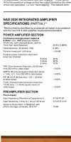
Just to calculate the need for power vs sensitivity speakers.
 

Attachments

  • 2021_10_23_12.17.17.jpg
    2021_10_23_12.17.17.jpg
    420.9 KB · Views: 75
OP
P

ppataki

Major Contributor
Joined
Aug 7, 2019
Messages
1,249
Likes
1,415
Location
Budapest
Then when you are done, this is hardly something for you to worry about. He he.:)


I think even an old vintage classic like this would fix the "steak".


Depends on what type of music you are listening to (very transient or not), volume, listening room, how "picky" you are and so on. The usual stuff, in other words.
Just to calculate the need for power vs sensitivity speakers.
Actually I am not too worried about this, I have a Hypex Ncore NC250MP amp, it shall be able to drive the line arrays pretty well - we shall see at the end, whenever the project will finish....
 
Top Bottom