• WANTED: Happy members who like to discuss audio and other topics related to our interest. Desire to learn and share knowledge of science required. There are many reviews of audio hardware and expert members to help answer your questions. Click here to have your audio equipment measured for free!

Lavoce SSF153.00 15" based dual opposed subwoofer project

ppataki

Major Contributor
Joined
Aug 7, 2019
Messages
1,481
Likes
1,736
Location
Budapest
I am excited to share my next project here! :)
After converting my MCLAs to a sub I have decided to look for a more traditional approach to subs - hence the below project came to my mind
I have designed and built several dual opposed subwoofers (DOS) already - I can say I really love this design

This time I am going to use two Lavoce SSF153.00 (4 ohm version) 15" drivers - they shall arrive early next week
I will put them in a sealed cabinet using 18mm MDF with a size of 630 x 450 x 400 mm

1704742551751.png


I will use a Sabaj A30A full digital amp to drive them with an approx. max power of 450W which will yield 105dB SPL at 1 meter at 24Hz

1704742648572.png


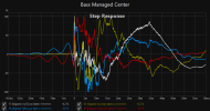
At around 70% of the xmax of this driver:
(so I expect low distortion)

1704742688342.png


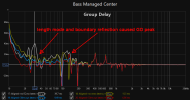
Group delay:

1704742721071.png


I am planning to cross the sub at 80Hz with my main system in the living room
The sub will be placed in the front in-between the Ikea Besta storage units (they actually hold all my gear including the PC and the audio stuff)

Build will start this week or latest next week, stay tuned!
 
WAF for something like this.
Actually that is a good point that I forgot to mention

If this project ends well (=if the cabinet is going to stay in the living room) then I already have an idea about how to increase its WAF:

If you check the photo of my living room you will see that the two Ikea Besta units have Laxviken doors
The plan is that I will buy a third Laxviken door, cut it to match the size of the front of the sub, do the cutout for the driver, do some rounding, do some paintjob and at the end the front will look exactly like the two Besta units on the sides :)
Seems pretty smart to me. You could even do white cloth grilles over the holes to minimize the visual impact. Nice setup!
 
Low Qtc was a design purpose in order to lower the overall power need
(Bigger sealed box = lower Qtc = lower power input needed to achieve a given output)
 
When I made my sub, I used MDF. I wish that this video came out before that, because I would have used plywood instead.


I have time stamped it at 25:05. He also suggests some other strategies to deaden the walls.
 
When I made my sub, I used MDF. I wish that this video came out before that, because I would have used plywood instead.


I have time stamped it at 25:05. He also suggests some other strategies to deaden the walls.

Yes, that is a good catch
I have seen this video before starting my MCLA project back in the day. That's why that cabinet was created using 2x12mm baltic birch plywood with a layer of Green Glue in-between (to form a constrained-layer damping)

I have done a 'hammer test' with it, you can see it here:
Pretty cool actually!

For this DOS project I wanted to keep it simple and hassle-free, hence I just opted for the MDF cabinet but I will add a 4mm thick vibrodamping layer on all the inside surfaces - that does wonders too btw. (I have a hammer test about that too but did not upload it - I might actually do another one specifically for this project)

EDIT: I already got the MDF sheets:

20240106_120353.jpg
 
Last edited:
Update:

Both drivers have arrived safe and sound!

20240112_123930.jpg

20240112_124202.jpg

20240112_124226.jpg

20240112_124308.jpg


27Hz test tone:

Sounds great to me, no signs of manufacturing defect

Hopefully build can start this week, will keep you guys posted
 
The hardware part is done, see the pictures below:

20240113_151945.jpg

20240113_192205.jpg

20240113_195811.jpg

20240113_204007.jpg

20240113_205650.jpg

20240114_101237.jpg


Ignore the (lack of) the aesthetics, that will follow later once I decided if the new sub stays or not

So far my subjective experience:
- cabinet barely resonates (note: some anti-vibration feet shall arrive in the coming days, that will also ensure that the sub will have the same height as the Besta units)
- I have not yet calibrated it (only volume correction and a Linkwitz Transform filter) but it definitely sounds promising

Next steps:
- calibration: proper volume leveling, delay, phase, crossover then I will try EQ-ing both with REW and with Dirac Live although recently Dirac started to behave in a funky fashion, producing the notorious 'exclamation mark' issue....)
- measurements

I will post the measurements before/after calibration in a few days
 
Now let's see those measurements!
All measurement were done in the MLP

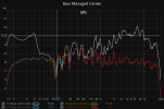
Sub with zero correction:
1705267536722.png


Sub crossed with mains at 80Hz, 24dB/octave, min. phase (using Jriver's DSP)

1705267599171.png


Dip appeared at 90Hz

Now let's see what Dirac could do with the situation:

1705267655241.png


Dip at 90Hz remained - I guess I will play around with the crossover (potentially trying linear phase too) to see if I can further remediate that
For the time being I am fine with these results

Let's see the Group delay:

1705267756071.png


Pretty good down to 26Hz or so

Waterfall (set to 400ms)

1705267824151.png


I might try some notch filters to fight those resonances later on - but again, I think this is not too bad

Spectrogram:

1705267915097.png


There is a 10ms peak energy time delay - I have seen many system with subs with way worse results

Distortion (%):

1705268038243.png


There is one peak at around 30Hz, other than that I am happy :)

Distortion (SPL):

1705268127660.png


Overall, I am pretty happy with these results
I am now fiddling around with setting a low shelf ('target curve') to taste - that will take days or even weeks

Further next steps:
- Once the shock absorber feet arrive in the coming days I will listen and measure if they make any difference at all
- Continuous fine-tuning of the low-end + considering the notch filters

At this point I think this beast is a keeper - in that case I will also need to fix the aesthetics as mentioned in post #3
Note: I consider the above results especially great if I take into account the fact that the whole thing cost me less than 500 EUR....
 
That looks excellent! What do you think is causing that dip at 90Hz, given that it was not there before the crossover was applied?
 
That looks excellent!
Thank you! :)

What do you think is causing that dip at 90Hz, given that it was not there before the crossover was applied?
It is not there in the sub's response and it is not there in the fronts' response either - so it is a phase issue induced by the crossover
I think this is 'normal' since minimum phase crossovers do have a huge impact on the phase curve (every 6dB/octave cut creates a 90° shift in the phase curve so 24dB/octave = 4*90° = 360°).
I will play around with the crossover settings: changing the frequency and changing the slope and will see what happens
Also I will try linear phase crossover (=no impact on the phase curve but elevated pre-ringing), potentially using any of these: CraveEQ, DDMF GrandEQ, T-Racks Linear Phase EQ
Btw. I am not too worried about that dip since it is relatively narrow but anyway it will be interesting to see if I can fix that (or make it even worse.... :))
 
It is not there in the sub's response and it is not there in the fronts' response either - so it is a phase issue induced by the crossover
Use the impulse alignment tool in REW and you should be able to find a delay that smooths that out.
 
Use the impulse alignment tool in REW and you should be able to find a delay that smooths that out.

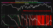
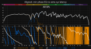
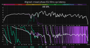
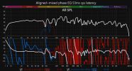
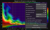
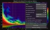
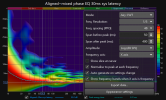
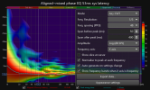
Yes, it's "possible" to optimize further with mixed phase equalization -- while incurring somewhat minimal side-effects -- but, there are other important contributing factors such as the room acoustics... i.e. How much does room coupling mangle the bass response?

Plots below is an extension of a prior xo test study exercise I did in another thread: https://www.audiosciencereview.com/...put-cant-hear-a-difference.51087/post-1839167

1705405118776.png 1705405124391.png 1705405127968.png 1705405131648.png 1705405135017.png 1705405138075.png 1705405141383.png 1705405144556.png 1705405147845.png 1705405151018.png 1705405154491.png 1705405157587.png 1705405160735.png 1705405163810.png 1705405177412.png

Forcing a flatter bass GD well past the previously created 30ms FIR filters is probably too little of an improvement -- some side effects are more easily visualized in the last wavelet spectrogram. Because this is part of a 5.1 MCH setup, 53ms "extra latency" considers all 6 output channel delays that require post adjustment.

MDAT measurement set:
 
Last edited:
Thanks @neRok and @ernestcarl
I will probably not invest too much time and effort in this since the dip is not really annoying - however I will definitely post if I manage to get any better results

Today the isolator feet have arrived so I will measure/listen to those first (and will comment on them here of course)
I am very skeptical but let's see (I can send them back anytime so I am not worried)

20240116_130712.jpg

20240116_130802.jpg

20240116_130821.jpg
 
So let's see the measurements with/without the Swissonic Riser XL (all measurements made in the MLP)

Does it make a difference? The answer is Yes
It does have a visible impact on the Waterfall plot and on the T60M curve
It did not have an impact on the other graphs

The waterfall comparison is best done with an animation:

waterfall animation.gif


I have set the time to 1000ms so it is easy to see the difference in the decay

And here is the T60M comparison (highlighted with the Riser XL)

T60M.png


I also tested it using the Vibrometer app on my phone
First I placed the phone on the floor next to the sub and played a 27Hz test tone loud enough that all the windows were audibly rattling in the room
The app barely noticed anything, max values were 0.3 with or without the feet

Then I put the phone on the sub itself:
- without the Riser XL the peak value was 2.7
- with the Riser XL it was 3.2
The mean value was also a bit higher with the Riser XL

Please correct me if I am wrong but I guess that this means that when using the Riser XL less vibration was transferred to the floor and hence the sub itself was vibrating more

Overall these are not huge differences but good enough for me to keep them
Based on the above, I would recommend the Swissonic Riser XL
 
I managed to solve the crossover 'issue' yesterday. I even found two solutions that worked equally well and I did not even have to change the crossover settings...
I will share both solutions below and the measurements too.

Solution 1: I applied a minimum phase low-shelf filter to the fronts and I applied another minimum phase low-shelf filter to the sub - the interaction of those two shelf filters actually changed the phase in a way that totally fixed the frequency curve

Solution 2: use linear phase crossover (with the same settings) - in this case there is no need for a low-shelf filter for the fronts and the frequency curve just looks fine (with the exception of a small hump)

Now the measurements (all at the MLP):

Frequency response

1705506341103.png


There is a small hump with linear phase crossover between 80 and 90Hz but that can easily be fixed (did not bother)
The most important point here is that there are no dips up to 150Hz!

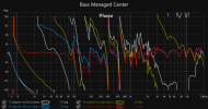
Phase

1705506568087.png


Linear phase looks better (less rotation)

Distortion

1705506636736.png


Both look excellent to me

Group delay

1705506710920.png


Again, linear phase looks a bit better


Spectrogram

ezgif-7-625d9c9226.gif


Much lower peak energy delay with linear phase but more pre-ringing (as expected) - but it is totally not audible

Overall I am extremely happy with both :)

Subjectively speaking I think I like the linear phase version better
Next step (apart from the aesthetics) is to play with some notch filters to fight the longer decay times
 
Back
Top Bottom