• WANTED: Happy members who like to discuss audio and other topics related to our interest. Desire to learn and share knowledge of science required. There are many reviews of audio hardware and expert members to help answer your questions. Click here to have your audio equipment measured for free!

Multi-Sub Optimizer (MSO): Lessons Learned, Tips & Tricks

kiwifi

Active Member
Joined
Apr 21, 2021
Messages
238
Likes
196
Every time I use Multi-Sub Optimizer (MSO) I learn something new, or maybe I just forget what I learned last time!

I don't want to repeat what is already available in the MSO documentation and online videos, but I thought it might be useful to create this thread to gather lessons learned from those who have successfully used MSO. Somewhere to document tips and tricks to get the best out of the software.
 
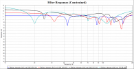
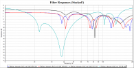
Plot the filter responses. This allows you can easily see when PEQ filters are stacked on top of each other resulting in excessive cuts in gain and poor use of the available PEQ filters
Stacked Filters.png

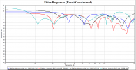
You can constrain the total PEQ cut under Optimization Options:Constraints
Constrained.png

But the result will be different depending on whether you "Reset All Filter Parameters" before starting an optimization or stick with the results of the last optimization.
Reset+Constrained.png

The filters that MSO generates in a sub-only configuration are very sensitive to the Fixed Reference Level that you set under Optimization Options:Method. For consistent comparison of one result to the next it is best to reset all filter parameters before the start of each optimization run.
 
The filters that MSO generates in a sub-only configuration are very sensitive to the Fixed Reference Level that you set under Optimization Options:Method. For consistent comparison of one result to the next it is best to reset all filter parameters before the start of each optimization run.

In theory, this should not happen. In saying that, I'm assuming that you're creating your configuration with the Configuration Wizard, and you're using MSO version 1.1.6 or later. See the release notes for that version.

The reference level is established by the shared gain block created by the Configuration Wizard. This gain block has a huge 0+/-24 dB adjustment range to allow for a wide range of reference levels. This behavior is different from, say, REW. In REW, if your target curve is below the measurement level and you allow the PEQs to only have attenuation (no gain), REW will use PEQs to do the equivalent of a gain adjustment. MSO uses gain blocks to adjust gain, to allow you to get the most out of the PEQs that you have. In the end, you just use the "minimal gain settings" in the filter report, which throws away the shared gain block anyway. See Why Specify a Reference Level if We're Just Going to Throw it Away? for an explanation of why a reference level is specified in MSO.

Overall results from one optimization to the next should be similar, but not identical to one another. Individual filters can vary all over the place from one optimization to the next. Variations from one optimization run to the next are due to the usage of a random number generator in the optimizer. A similar situation occurs with DLBC, which (they say) uses a genetic algorithm (which also requires random number generation).
 
Last edited:
In theory, this should not happen. In saying that, I'm assuming that you're creating your configuration with the Configuration Wizard, and you're using MSO version 1.1.6 or later. See the release notes for that version.

The reference level is established by the shared gain block created by the Configuration Wizard. This gain block has a huge 0+/-24 dB adjustment range to allow for a wide range of reference levels. This behavior is different from, say, REW. In REW, if your target curve is below the measurement level and you allow the PEQs to only have attenuation (no gain), REW will use PEQs to do the equivalent of a gain adjustment. MSO uses gain blocks to adjust gain, to allow you to get the most out of the PEQs that you have. In the end, you just use the "minimal gain settings" in the filter report, which throws away the shared gain block anyway. See Why Specify a Reference Level if We're Just Going to Throw it Away? for an explanation of why a reference level is specified in MSO.
First of all, thanks for a wonderful piece of software. My subs have never sounded better!

Yes, I am using the latest version (1.1.11) with the configuration wizard. I did see PEQ stacking happen occasionally, with what I thought was reasonable choice of Reference Level, which is why I found that graphing the filters was so useful, just to monitor what was happening.

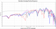
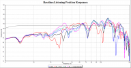
Baseline.png
I read somewhere that the Reference Level is set at the Max frequency of the "Criteria: Frequency Range to Optimize" (160Hz in my case) and mapped to the Target Curve. So I try to "best fit" my target curve to the (Baseline) measured response by eye, and then check that my choice of Reference Level does not result in any PEQ filters hitting their limits of attenuation (if possible). It would be nice if the software could select the optimum Reference Level in a Sub-Only configuration.

I understand that the shared gain block can be ignored in the end, because the minimal gain settings will get all the subs aligned with each other. However, the use of attenuation only PEQ filters will reduce the power output of each sub overall (the area under the curve is reduced by MSO) such that some of that shared gain will need to be put back in, to bring the overall level of (all) the subs back up to the measured 75dB at the MLP.
 
Last edited:
  • I did see PEQ stacking happen occasionally, with what I thought was reasonable choice of Reference Level, which is why I found that graphing the filters was so useful, just to monitor what was happening.

I'd like to clarify that there is a difference between the "reference level" that you choose to figure out by eyeballing what the maximum boost and cut of the PEQ filters should be, and the reference level that you enter into the optimization options dialog. Once you figure out the maximum PEQ boost and cut by eyeballing, the reference level number you enter into the optimization options dialog is irrelevant to the final result.

I read somewhere that the Reference Level is set at the Max frequency of the "Criteria: Frequency Range to Optimize" (160Hz in my case) and mapped to the Target Curve.

This is true.

So I try to "best fit" my target curve to the (Baseline) measured response by eye, and then check that my choice of Reference Level does not result in any PEQ filters hitting their limits of attenuation (if possible). It would be nice if the software could select the optimum Reference Level in a Sub-Only configuration.

Regarding the reference level that you enter into the optimization options dialog, there is no optimum value. Regarding the "eyeball" reference level for picking the maximum boost and cut of the PEQs, the optimum level depends on how much PEQ boost or cut you're willing to have. Different users have different needs determined by their situation. "Stacking" is prevented by using the Constraints page of the optimization options dialog to set the maximum total PEQ boost and cut to be just a hair larger than the maximum individual PEQ boost and cut respectively.

Speaking of this, your data indicate that your modal problems are pretty minimal, but that low-frequency boost (or high-frequency cut) is needed. In your case, this is best done not with PEQs, but with either a shared LF shelving filter with LF boost, or a shared HF shelving filter with HF cut. Just one shared shelving filter would do a lot to reach your target curve, with PEQs used only for cleanup of modal issues.

I'd suggest either:
  • A shared LF shelving filter of type "LF Shelf Variable Q Second-Order (Alt)", or
  • A shared HF shelving filter of type "HF Shelf Variable Q Second-Order (Alt)"
These would have a center frequency of about 40 Hz (the "half boost/half cut frequency"). If you use an LF shelf, it would have an LF boost of about 8 dB, while an HF shelf would have an HF cut of about 8 dB. Q should be between 0.5 and 0.707. If you have boatloads of additional adjustable sub amp gain available, the HF shelf with HF attenuation is the way to go, as this would minimize the required voltage swing of the miniDSP to reach a given SPL. The miniDSP must never be allowed to clip before the power amp does.

You can get a good idea of what the final shelving parameters should be (to limit the parameter ranges for the optimizer) by using the tuning feature, as described in the docs about the target curve example. You should be able to do a lot with just this one shelving filter. The tuning function will show the effects of the shelving filter in real time. Try tuning using the target curve example first.

To reiterate, a claim that the reference level number you enter into the optimization options dialog is critically important is not a lesson to be learned, but a myth. Prior to 1.1.6, exceeding gain block limits could be a problem, but with 1.1.6 and later, this is no longer a concern.
 
Last edited:
I'd like to clarify that there is a difference between the "reference level" that you choose to figure out by eyeballing what the maximum boost and cut of the PEQ filters should be, and the reference level that you enter into the optimization options dialog. Once you figure out the maximum PEQ boost and cut by eyeballing, the reference level number you enter into the optimization options dialog is irrelevant to the final result.
I am using attenuation only PEQ filters. I had been setting the individual PEQ limits based on the capability of my hardware (QSC DSP-4) rather than observing the baseline measured response.
Regarding the reference level that you enter into the optimization options dialog, there is no optimum value. Regarding the "eyeball" reference level for picking the maximum boost and cut of the PEQs, the optimum level depends on how much PEQ boost or cut you're willing to have. Different users have different needs determined by their situation. "Stacking" is prevented by using the Constraints page of the optimization options dialog to set the maximum total PEQ boost and cut to be just a hair larger than the maximum individual PEQ boost and cut respectively.
Understood!
Speaking of this, your data indicate that your modal problems are pretty minimal, but that low-frequency boost (or high-frequency cut) is needed. In your case, this is best done not with PEQs, but with either a shared LF shelving filter with LF boost, or a shared HF shelving filter with HF cut. Just one shared shelving filter would do a lot to reach your target curve, with PEQs used only for cleanup of modal issues.
Thanks! I had not considered using a shared filter.

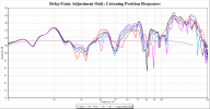
If I first create at config with just delays and gains (all PEQ's removed) it is much easier to see the overall (room + subs) response.
DelayGainConfig.PNGDelay_Gain.pngBaseline.png

Wouldn't starting with this view rather than the raw baseline, make it easier to estimate the required PEQ limits and insert any shared filters?
 
Last edited:
If I first create at config with just delays and gains (all PEQ's removed) it is much easier to see the overall (room + subs) response.

[...]

Wouldn't starting with this view rather than the raw baseline, make it easier to estimate the required PEQ limits and insert any shared filters?

If you select the "Neglect the MLP target curve" option on the Method page of the Optimization Options dialog, this will prevent MSO from trying to force the MLP response to the target curve. When using this option, MSO only tries to minimize seat-to-seat variation regardless of the target curve. It requires that you use only filters whose magnitude response is frequency-independent (gain and delay blocks, inversions and all-pass filters).

If you don't use this option, even with only gain blocks and delays, MSO will still try to do whatever it can to flatten the MLP response. If I understand your question correctly, this isn't what you want (at least for the preliminary step of finding the "overall (room + subs) response").

There's no commonly-accepted definition of the "overall (room + subs) response" when multiple subs are used, since it depends on how the subs combine with one another due to delays and so on. But you could use the above option with only per-sub delays and a shared gain block to get something that might approximate the concept. The shared gain block is needed to set the reference level, which is the MLP response value at the highest optimization frequency. The delay blocks would then only be used to minimize seat-to-seat variation, not for response shaping.
 
Last edited:
If you select the "Neglect the MLP target curve" option on the Method page of the Optimization Options dialog, this will prevent MSO from trying to force the MLP response to the target curve. When using this option, MSO only tries to minimize seat-to-seat variation regardless of the target curve. It requires that you use only filters whose magnitude response is frequency-independent (gain and delay blocks, inversions and all-pass filters).

If you don't use this option, even with only gain blocks and delays, MSO will still try to do whatever it can to flatten the MLP response. If I understand your question correctly, this isn't what you want (at least for the preliminary step of finding the "overall (room + subs) response").

There's no commonly-accepted definition of the "overall (room + subs) response" when multiple subs are used, since it depends on how the subs combine with one another due to delays and so on. But you could use the above option with only per-sub delays and a shared gain block to get something that might approximate the concept. The shared gain block is needed to set the reference level, which is the MLP response value at the highest optimization frequency. The delay blocks would then only be used to minimize seat-to-seat variation, not for response shaping.
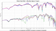
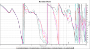
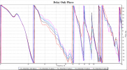
Thanks for the "Neglect the MLP target curve" tip. Intuitively, it seems logical to time align the subs to see their combined response at the listening positions, although I realize that the final time alignment when the PEQ filters are active may end up being different in order to achieve the desired response.

DelayGainCompare.pngBaseline_Phase.pngDelayGain_Phase.png

I think this Delay/Gain view does make the combined frequency response across the measured positions easier to visualize, especially when I am considering what type and how many shared filters to include. Up to now I have just been adding them to a configuration one by one, until their effect on the final result seems to be negligible.
 
Last edited:
@andyc56 My apologies. I wasn't able to PM you or find any other way to report this MSO bug, so I am posting it here...

It appears that the limit set in "Constraints:Restrict total PEQ cut" only applies between the frequencies defined by "Criteria:Frequency range to optimize"
If the "PEQ Parameter Limits:Minimum center frequency" or "PEQ Parameter Limits:Maximum center frequency" are outside of the "frequency range to optimize" then filters can be placed outside of the frequency range being optimized (while still affecting the optimization range) but they are not subject to the total cut limit.

The range over which "Constraints:Restrict total PEQ cut" is applied should be the range
MIN (Frequency range to optimize min limit || PEQ min center frequency range) to MAX (Frequency range to optimize max limit || PEQ max center frequency range). Alternatively you could set the range equal to the measurements frequency range or allow the frequency range over which the limit operates to be set explicitly by the user.

This issue may also apply to "Constraints:Restrict total PEQ boost"
 
Last edited:
@andyc56 My apologies. I wasn't able to PM you or find any other way to report this MSO bug, so I am posting it here...

It appears that the limit set in "Constraints:Restrict total PEQ cut" only applies between the frequencies defined by "Criteria:Frequency range to optimize"
If the "PEQ Parameter Limits:Minimum center frequency" or "PEQ Parameter Limits:Maximum center frequency" are outside of the "frequency range to optimize" then filters can be placed outside of the frequency range being optimized (while still affecting the optimization range) but they are not subject to the total cut limit.

That's by design. The tutorial discusses setting the PEQ min and max center frequencies here.

MSO Tutorial said:
What range of PEQ center frequencies do we need? If we allow the PEQ center frequencies to go outside the optimization frequency range, we will lose some control of what is happening there, as MSO normally does no calculations outside the optimization frequency range. Under this condition, the PEQs could make some changes outside the optimization limits that we don't want. Likewise, if we don't allow the PEQs to cover the full optimization frequency range, we may not be able to take full advantage of what the PEQs can do for us within this frequency range. It stands to reason that a good rule of thumb is to make the allowable center frequency range of the PEQs the same as the optimization frequency range.

The range over which "Constraints:Restrict total PEQ cut" is applied should be the range
MIN (Frequency range to optimize min limit || PEQ min center frequency range) to MAX (Frequency range to optimize max limit || PEQ max center frequency range). Alternatively you could set the range equal to the measurements frequency range or allow the frequency range over which the limit operates to be set explicitly by the user.

This issue may also apply to "Constraints:Restrict total PEQ boost"

What specifically are you trying to accomplish that requires PEQ center frequencies outside the optimization frequency range? This generally isn't a good idea, unless you lock the parameters of the PEQs to prevent the optimizer from altering them.
 
That's by design. The tutorial discusses setting the PEQ min and max center frequencies here.
Sorry, but that behavior wasn't what I was expecting. At first glace it didn't seem like a bad idea! It is also quite easy to do, if you begin by trying to optimize a wide range and then later decide to narrow it down.
What specifically are you trying to accomplish that requires PEQ center frequencies outside the optimization frequency range? This generally isn't a good idea, unless you lock the parameters of the PEQs to prevent the optimizer from altering them.
I agree with you regarding locked PEQ's outside of the optimization range, but why allow MSO to assign unlocked PEQ's center frequencies outside of the optimization range at all, especially if they are not going to be subject to the same limits as those inside?
 
Last edited:
In no particular order here are the things I have learned after like many others reading the docs and watching the videos. Thanks Andy for this awesome tool - finally I am getting a chance to dive deep with it after a few years of (way too much!) DIY home renos.

Great idea for a thread - my thoughts and observations:

- MSO can really quickly show you the impact of trying to mix ported, sealed, passive radiator subs for us less familiar with the impact of phase and sub speaker design - I have learned a ton here and found it very enlightening. I have given up on trying to include an older but powerful small sub with passive radiators (a Paradigm Seismic 12) with 2 SVS sealed subs. The rate of change of phase (aka group delay) is simply too different between these subs at different frequencies to easily integrate them together and MSO let me try many different options very quickly to see the differences. The Paradigm is relegated to the cottage system and I have no regrets. Even quirky combinations of all pass filters could not provide a smooth integration - any additional subs will be sealed to ensure matching phase and group delay
- play around manually with settings for filters, polarity etc - the more you do this, the more you gain an understanding of the impact of the results in the MSO optimization routine
- a polarity inversion of the back sub(s) really works and MSO can easily demonstrate this - try it before you run your optimizations
- plotting the filters directly on the measurements plots provides a fantastic and real time view into what is required to flatten the frequency response, and how evenly the load is being distributed amongst the various subs. A bit of tweaking and possibly hard coding the gain range can also allow you to force more output to larger more powerful subs to balance headroom, and also to potentially reduce relative vol for near field subs if they are more easily localized (for me I love the immediate physical impact of nearfield subs and this allows be to make sure MSO is not shifting the power to the far field subs which is is want to do if you don't constrain it)
- I would love to see a feature/parameter in MSO that minimizes relative gains between subs (i.e. one sub cannot have a greater gain variance to another sub by 6-10db or so to constrain this automatically). You can constrain subs to have a max gain amount but only relative to itself - relative to other subs is actually more useful IMO
- change the color and line thickness of MLP or other key seat positions on your charts so you can easily see it through the noise
- set up all your charting preferences in your first chart - these will be copied to all subsequent cloned configurations and charts saving you a ton of time. Thing to set are vertical and horizontal axis range, line colors, filter channel traces, target traces, etc
- follow the approach proposed by Jeff (fattire) in his latest posts and videos (thanks Jeff!) to use shared filters and then a small number of individual sub filters to get the best results.
- you can get extremely satisfying results from only 2 subs, but ideally they are not both at the front of the room
- not really an MSO trick: people spend a lot of money with monstrous ported subs in the front of the room such that they can "feel" the base. You can get a ton of visceral impact with a nearfield sub or two (or more) that is way smaller tucked behind your seats along with a sub or two in front- careful tweaking with MSO can ensure that the nearfield subs are not turned down too low or cancelling key frequencies with the front subs. If you think you can localize the nearfield subs, simply add a Low pass filter with steep slope (24db/octave or higher) centered at 80Hz prior to measuring your subs, and make sure the sub is not causing anything near it to buzz or rattle to give it away.
- don't be shocked when you need to filter some frequencies 20db or more - typically these will be the first or second order length or width modes in the 15 to 50 Hz range. My 28 foot long room rings at 16 hz and 32 Hz which gives a ton of natural boost to sealed subs located on front or back wall. It may seem crazy to reduce the output of that massive ported sub tuned to 16Hz when you spent so much money on it - but trust me you will get shockingly powerful low and clear, smooth and extremely deep and satisfying bass when you do this and follow MSO recommendations - and the bonus is a ton of headroom at these lowest of frequencies
- you can use MSO to experiment and tune for single subs and single seat positions too, and even with bi-amped large stereo only speakers if you introduce a dsp on the LF portions
 
In no particular order here are the things I have learned after like many others reading the docs and watching the videos. Thanks Andy for this awesome tool - finally I am getting a chance to dive deep with it after a few years of (way too much!) DIY home renos.

Great idea for a thread - my thoughts and observations:

- MSO can really quickly show you the impact of trying to mix ported, sealed, passive radiator subs for us less familiar with the impact of phase and sub speaker design - I have learned a ton here and found it very enlightening. I have given up on trying to include an older but powerful small sub with passive radiators (a Paradigm Seismic 12) with 2 SVS sealed subs. The rate of change of phase (aka group delay) is simply too different between these subs at different frequencies to easily integrate them together and MSO let me try many different options very quickly to see the differences.
I absolutely agree. I have just plugged the port on my SVS PB-1000 to integrate it with three different sealed subwoofers. With the port open, MSO was adding a -30dB PEQ at the port tuning frequency because of that phase shift. Easy to see from the plotted filter responses.
- follow the approach proposed by Jeff (fattire) in his latest posts and videos (thanks Jeff!) to use shared filters and then a small number of individual sub filters to get the best results.
Do you have a link?
 
Do you have a link?

Don't have the time to find link at the moment but Jeff (fattire) posted this on AVSForum in one of the main MSO threads sometime in July or August 2022.

Gist of it is to:
- use 5 to 10 shared filters on the input channels on the dsp which apply to all subs that can have a high gain drop (up to -20 db)
- then add a small number of relatively lower gain (say 2 to 4 filters of up to -6db or so) for each subs output that are different for each sub. Max Q of 8.6
- Also to experiment with 1 or 2 low Q (Q = .1 to 3 or 4) all pass filters for 1st or 2nd order (these introduce a phase shift of 90 or 180 degrees respectively).
- Don't includegain "filters" on the output channels, but can include delays.

The goal here is to balance the output from all subs as closely as possible.


My latest run using this approach is below. Both subs are working together perfectly balanced between 15 and 62 Hz (you can see the blue and red filter channels) and a few minor deviations around 68Hz and 92 Hz.

BTW ignore the results above 100 Hz - will be re-measuring over the holidays using a new approach that bypasses my processor's LPF - setting it to 160Hz was not enough to get decent results above 100Hz. To do this, I will temporarily change the R speaker to Large and connect the R pre-out into the subs directly. This is another good trick i read somewhere that I wish I had figured out before the last measurement runs!

1671112332828.png
 
Last edited:
Don't have the time to find link at the moment but Jeff (fattire) posted this on AVSForum in one of the main MSO threads sometime in July or August 2022.

Gist of it is to:
- use 5 to 10 shared filters on the input channels on the dsp which apply to all subs that can have a high gain drop (up to -20 db)
- then add a small number of relatively lower gain (say 2 to 4 filters of up to -6db or so) for each subs output that are different for each sub. Max Q of 8.6
- Also to experiment with 1 or 2 low Q (Q = .1 to 3 or 4) all pass filters for 1st or 2nd order (these introduce a phase shift of 90 or 180 degrees respectively).
- Don't includegain "filters" on the output channels, but can include delays.

The goal here is to balance the output from all subs as closely as possible.
Not including gain blocks in the individual sub-woofer output channels is definitely counter intuitive but you seem to have got a good result anyway. It probably relies on having pretty good gain matching at the outset.
My latest run using this approach is below. Both subs are working together perfectly balanced between 15 and 62 Hz (you can see the blue and red filter channels) and a few minor deviations around 68Hz and 92 Hz.

BTW ignore the results above 100 Hz - will be re-measuring over the holidays using a new approach that bypasses my processor's LPF - setting it to 160Hz was not enough to get decent results above 100Hz. To do this, I will temporarily change the R speaker to Large and connect the R pre-out into the subs directly. This is another good trick i read somewhere that I wish I had figured out before the last measurement runs!
I am not sure how you are generating your REW measurement signals, but if you are using an external DAC interface (ie Motu M4) then you can bypass the AVR and feed the signal into the sub(s) or the DSP feeding the subs directly. If you don't have a separate amp for your acoustic reference, then set the AVR to pure direct mode and use a spare AVR input.

If your DSP does not have a fixed latency then you may also want to try adding all the filter blocks that you expect to use into the signal path, but with zero gains and delays, before taking the baseline measurements.
 
What specifically are you trying to accomplish that requires PEQ center frequencies outside the optimization frequency range? This generally isn't a good idea, unless you lock the parameters of the PEQs to prevent the optimizer from altering them.
@andyc56
I would like to be able to first optimize the shared filters over the range 10 - 200Hz, with all the sub-woofer filters reset and locked.
Then I want to lock the shared filters and unlock the sub-woofer filters, but now only optimize (allocate unlocked filters) over the range 20 - 120Hz.

In this scenario, if I try to set the max PEQ center frequency to match the lower optimization range at 120Hz, it won't allow this unless it first sets all shared PEQ center frequencies to <= 120Hz. But if I leave the max PEQ center frequency limit set to 200Hz and reduce the optimization range to 120Hz, MSO will allocate some filters outside of the optimization range, i.e. with center frequencies greater than 120Hz and to make things worse, these filters are not subject to the Total PEQ cut limits.

The problem is that MSO is allowed to allocate filters with new center frequencies outside of the limits set by the optimization range. This is the "bug" that need to be fixed.
 
hi @kiwifi may i borrow your thread for a second? i have a couple of very simple questions about MSO (that i am planning to use but i havent yet) for you or anyone following this thread. I could not find any other MSO specific thread at ASR:
1. i cannot find anywhere the specifics about how to do the measurements except in Jeff Mery video tutorials, where he says that the measurements are made with the UMIK-1 pointing upwards and with the 90° cal file. Is this correct? is this correct as well for the mains measurements?
2. i plan to follow the minidsp tutorial (i will be using 2 subs and a DDRC-24). Any opinions about this tutorial? i see some slight differences like for instance "measure in the center of the main listening area + 3 positions around the main listening area" (minidsp) vs "do one measurement at each listening position" (Jeff Mery videos and other sources). is it relevant? if yes, who is right?


thanks a lot!
1 is correct mic in and 90 degree cal file

2 both are correct. You could do 3- however Many measurments you like. But beyond you listening positions it gets somewhat pointless.
 
  • Like
Reactions: MCH
2. i plan to follow the minidsp tutorial (i will be using 2 subs and a DDRC-24). Any opinions about this tutorial? i see some slight differences like for instance "measure in the center of the main listening area + 3 positions around the main listening area" (minidsp) vs "do one measurement at each listening position" (Jeff Mery videos and other sources). is it relevant? if yes, who is right?

MSO evens out the bass response across multiple seating positions. If you only have one seat, then measurements round that one seat will widen the "sweet spot"
You should always measure at least P = N + 1 positions where N = the number of sub-woofers. However, increasing the number of measurements beyond P starts to have diminishing returns.
You also have the option to adjust the weighting (importance) that MSO assigns to each measurement position if you want to. This will produce a better response in one (or more) positions at the expense of the others. Not something that I have ever used.
 
  • Like
Reactions: MCH
MSO evens out the bass response across multiple seating positions. If you only have one seat, then measurements round that one seat will widen the "sweet spot"
You should always measure at least P = N + 1 positions where N = the number of sub-woofers. However, increasing the number of measurements beyond P starts to have diminishing returns.
You also have the option to adjust the weighting (importance) that MSO assigns to each measurement position if you want to. This will produce a better response in one (or more) positions at the expense of the others. Not something that I have ever used.
Thank you both, it makes sense.
As i only have two subs and a 3 seats couch, will measure the 3 listening positions and maybe a few extra measurements if I find the weighting option you mention. Thanks!
 
Back
Top Bottom