• WANTED: Happy members who like to discuss audio and other topics related to our interest. Desire to learn and share knowledge of science required. There are many reviews of audio hardware and expert members to help answer your questions. Click here to have your audio equipment measured for free!

Minimum Phase

dasdoing

Major Contributor
Joined
May 20, 2020
Messages
4,301
Likes
2,774
Location
Salvador-Bahia-Brasil
"in time"!

These babies:

View attachment 306670

But "use with caution" as the author reminds :)

this gives you more control? I get that
but it creates an aditional resonance from what I see. and again, whatever I do to move these forward, they will be "spiky" in the filter. And I always hear those in the result.

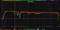
If you want to show me what you can do with this, take this Mdat and correct one of these 3 delays between 200-500Hz and give me the filter to test. just one of these is enough.


OCA

Addicted to Fun and Learning
Forum Donor
Joined
Feb 2, 2020
Messages
679
Likes
499
Location
Germany
this gives you more control? I get that
but it creates an aditional resonance from what I see. and again, whatever I do to move these forward, they will be "spiky" in the filter. And I always hear those in the result.

If you want to show me what you can do with this, take this Mdat and correct one of these 3 delays between 200-500Hz and give me the filter to test. just one of these is enough.

:cool: II will rise to the challenge!
 

BR52

Addicted to Fun and Learning
Joined
Apr 3, 2021
Messages
573
Likes
495
Location
Germany
View attachment 306444

It is perfect, right?

But now let's assume the head is moved 1 cm. So the left ear receives the right speaker just a bit later.
So we get a slight different sum and comb filter.
Unfortunately we apply the previous correction filter on the new situation.
The resulting corrected pulse response (convolution of actual room/speaker pulse response with previous correction is now

View attachment 306445

and the frequency response is

View attachment 306446

So obviously now the perfect correction looks a little non-perfect.

I hope this little example demonstrates that all small-talk about a PERFECT correction is nonsense. A room correction should not try to correct reflections.
I suppose the computer between the ears will be astonished if he can discern this flawless signal, as he has been extensively trained to handle such "imperfection."
 

OCA

Addicted to Fun and Learning
Forum Donor
Joined
Feb 2, 2020
Messages
679
Likes
499
Location
Germany
this gives you more control? I get that
but it creates an aditional resonance from what I see. and again, whatever I do to move these forward, they will be "spiky" in the filter. And I always hear those in the result.

If you want to show me what you can do with this, take this Mdat and correct one of these 3 delays between 200-500Hz and give me the filter to test. just one of these is enough.

This is not a measurement though, it's some calcualtion, let's see how robust the EP will come out...
 

OCA

Addicted to Fun and Learning
Forum Donor
Joined
Feb 2, 2020
Messages
679
Likes
499
Location
Germany
this gives you more control? I get that
but it creates an aditional resonance from what I see. and again, whatever I do to move these forward, they will be "spiky" in the filter. And I always hear those in the result.

If you want to show me what you can do with this, take this Mdat and correct one of these 3 delays between 200-500Hz and give me the filter to test. just one of these is enough.

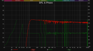
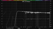
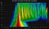
IR you've sent me was 44.1kHz, REW refused to convolve it with my 48kHz rePhase filter so I could not post the final spectrogram but the filter below efficiently improved the EP spikes and didn't seem to pre-echo in CWT (but that's still a theory):

rePhase settings
eNqVU8GOmzAQ/RXkUysRZAIENreq11bKfRWhARuwFtvUdjZNV/vvHZtsNmSjVXshmTfvjZ89My+k
0b/rToyOG0u2j/uYtFxhIFRPtkQKxkZOEBx4+2QPErHiIc+qrsy7pmUcGGuboljTpoMiq2hbBrbR
1i6rYsAVSI4FGFhGPGJuKNpIcEjI1lEjnI1+7L7/jKRWOvqSHOH5K3nj1M8oElohN01ohXgPwkc0
odRH/NdcsjcwDbXlzuF97D2sNqCeyJbGRCz8PJJB9MNqAmux4FqxSBvGTfRtHFe7M5iTWB3GMSbp
gw83WeJ/U7KP/0tdvos9cKtOrftMvfGUssDvh3OXHjNPpOF9PmdWF+I9OwtqnhT/TqZJSctrE9gM
ycEeDJc4c2T7QppTEPp2tFpOXFlwPIQMHGBbQqXlZz93v9Zdh031Q4DFB8F4LaEP2hBMA9i5lFA4
Pi78dULya+FrTJT2J3rnesK0+ANunjSlFb9B627U2mBulYYrTW9zN+kRjHCnIDMSUxbkNF6dhUqc
9TM+L1tezQ9jdeeOYLwLw3fB9jtY20Nz3qM7yeu9yBPfcaQvt8zBZMOOlRvf6PACTBjeXq4Z/LrT
5M9otTmnossWxeQoFNPH2bVPg+oPeGHy+hcssFfk
 
Last edited:

UliBru

Active Member
Technical Expert
Joined
Jul 10, 2019
Messages
124
Likes
338
If you want to show me what you can do with this, take this Mdat and correct one of these 3 delays between 200-500Hz and give me the filter to test. just one of these is enough.

What about attached EP?
 

Attachments

  • Comp264.679Q24.wav.zip
    123 KB · Views: 36

OCA

Addicted to Fun and Learning
Forum Donor
Joined
Feb 2, 2020
Messages
679
Likes
499
Location
Germany
What about attached EP?
That's a powerful inverse which would normally echo without the ultra-short right window trick! My compliments Dr. Uli!

Can you in practice really create a filter with 0.023ms window size in Acourate?
 

UliBru

Active Member
Technical Expert
Joined
Jul 10, 2019
Messages
124
Likes
338
That's a powerful inverse which would normally echo without the ultra-short right window trick! My compliments Dr. Uli!

Can you in practice really create a filter with 0.023ms window size in Acourate?

This is a quite sophisticated and proprietary algorithm in Acourate.
But ok, I tell you:
The right window gets squeezed with high pressure. As you know this creates heat. So the window gets cooled down heavily by some cryogenic treatment. Thus the window size shrinks even more. At the end the window is fixed by glueing. Welding would be better but it has the undesired side-effect to bring in heat again.
Ok? :D Just kidding.

Indeed I have simply checked the phase at the three frequencies, select one of them and created a 2nd order allpass with Q24 by comparing the phases. So Q24 does the job quite well. Then the (minphase) allpass is reversed and that's it.
In reality I would not use such filters. You can see it has a quite long ringing time. With the given mdat example the convolution is perfect. But if the pulse responses changes, e.g. change of listening position, and if then the frequency or Q changes then filter will show up a lot of preringing. And you can hear 250 Hz usually prettyx well.

At the given samplerate 44100 Hz the sampling time is 0.0226... ms. So such a short window would have the value 1 at a first sample and a value 0 at the next sample. A perfect rectangle window. For other window types the is no sample left to describe the window shape.
 

ernestcarl

Major Contributor
Joined
Sep 4, 2019
Messages
3,113
Likes
2,330
Location
Canada
Indeed I have simply checked the phase at the three frequencies, select one of them and created a 2nd order allpass with Q24 by comparing the phases. So Q24 does the job quite well. Then the (minphase) allpass is reversed and that's it.
In reality I would not use such filters. You can see it has a quite long ringing time. With the given mdat example the convolution is perfect. But if the pulse responses changes, e.g. change of listening position, and if then the frequency or Q changes then filter will show up a lot of preringing. And you can hear 250 Hz usually prettyx well.

At the given samplerate 44100 Hz the sampling time is 0.0226... ms. So such a short window would have the value 1 at a first sample and a value 0 at the next sample. A perfect rectangle window. For other window types the is no sample left to describe the window shape.

This seems to yield a close enough result:

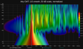
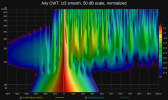
1692487199626.png


Yeah, we would be convolving an extreme filter on top of an already "extremely" corrected room response. The result looks passable in the graphs, but the more important question of real world applicability ensues. Then there is the psychoacoustics...


Other plot views:
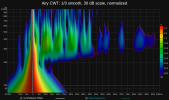
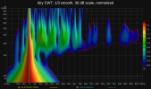
1692493163960.png 1692493170214.png 1692493664005.png 1692493178981.png 1692493453162.png


Small phase shift (simulating head/body position movement or speaker/environment change):
1692529577391.png 1692529584702.png 1692529589845.png
 
Last edited:
  • Like
Reactions: OCA

dasdoing

Major Contributor
Joined
May 20, 2020
Messages
4,301
Likes
2,774
Location
Salvador-Bahia-Brasil
IR you've sent me was 44.1kHz, REW refused to convolve it with my 48kHz rePhase filter so I could not post the final spectrogram but the filter below efficiently improved the EP spikes and didn't seem to pre-echo in CWT (but that's still a theory):

rePhase settings
eNqVU8GOmzAQ/RXkUysRZAIENreq11bKfRWhARuwFtvUdjZNV/vvHZtsNmSjVXshmTfvjZ89My+k
0b/rToyOG0u2j/uYtFxhIFRPtkQKxkZOEBx4+2QPErHiIc+qrsy7pmUcGGuboljTpoMiq2hbBrbR
1i6rYsAVSI4FGFhGPGJuKNpIcEjI1lEjnI1+7L7/jKRWOvqSHOH5K3nj1M8oElohN01ohXgPwkc0
odRH/NdcsjcwDbXlzuF97D2sNqCeyJbGRCz8PJJB9MNqAmux4FqxSBvGTfRtHFe7M5iTWB3GMSbp
gw83WeJ/U7KP/0tdvos9cKtOrftMvfGUssDvh3OXHjNPpOF9PmdWF+I9OwtqnhT/TqZJSctrE9gM
ycEeDJc4c2T7QppTEPp2tFpOXFlwPIQMHGBbQqXlZz93v9Zdh031Q4DFB8F4LaEP2hBMA9i5lFA4
Pi78dULya+FrTJT2J3rnesK0+ANunjSlFb9B627U2mBulYYrTW9zN+kRjHCnIDMSUxbkNF6dhUqc
9TM+L1tezQ9jdeeOYLwLw3fB9jtY20Nz3qM7yeu9yBPfcaQvt8zBZMOOlRvf6PACTBjeXq4Z/LrT
5M9otTmnossWxeQoFNPH2bVPg+oPeGHy+hcssFfk

This is a quite sophisticated and proprietary algorithm in Acourate.
But ok, I tell you:
The right window gets squeezed with high pressure. As you know this creates heat. So the window gets cooled down heavily by some cryogenic treatment. Thus the window size shrinks even more. At the end the window is fixed by glueing. Welding would be better but it has the undesired side-effect to bring in heat again.
Ok? :D Just kidding.

Indeed I have simply checked the phase at the three frequencies, select one of them and created a 2nd order allpass with Q24 by comparing the phases. So Q24 does the job quite well. Then the (minphase) allpass is reversed and that's it.
In reality I would not use such filters. You can see it has a quite long ringing time. With the given mdat example the convolution is perfect. But if the pulse responses changes, e.g. change of listening position, and if then the frequency or Q changes then filter will show up a lot of preringing. And you can hear 250 Hz usually prettyx well.

At the given samplerate 44100 Hz the sampling time is 0.0226... ms. So such a short window would have the value 1 at a first sample and a value 0 at the next sample. A perfect rectangle window. For other window types the is no sample left to describe the window shape.

sorry for the late reply guys,

these do in fact work on paper but create preringing.

Given that I now can rule these phase rotations out for being uncorrectable,

............"extremely" corrected room response [.........] Then there is the psychoacoustics.....

I do think that I finally have a method for REW.
I will text export the psychoacoustic response and invert it (actually target/psy-response). I do that 5 times in a row. then I export var response and do the same 3 times in a row. The result is a nearly linear phase sans the before-mentioned phase rotation.
I will probably create a new topic. I am still testing stuff.

EDIT: for the sub a total inversion is totally possible. I strongly advice correcting mains and sub separately. you can also create the perfect crossover this way
 
  • Like
Reactions: OCA

OCA

Addicted to Fun and Learning
Forum Donor
Joined
Feb 2, 2020
Messages
679
Likes
499
Location
Germany
sorry for the late reply guys,

these do in fact work on paper but create preringing.

Given that I now can rule these phase rotations out for being uncorrectable,


I do think that I finally have a method for REW.
I will text export the psychoacoustic response and invert it (actually target/psy-response). I do that 5 times in a row. then I export var response and do the same 3 times in a row. The result is a nearly linear phase sans the before-mentioned phase rotation.
I will probably create a new topic. I am still testing stuff.

EDIT: for the sub a total inversion is totally possible. I strongly advice correcting mains and sub separately. you can also create the perfect crossover this way
From a mathematical perspective, only minimum phase responses can undergo inversion. Ensuring the inversion of responses in their "minimum phase" forms guarantees safety, eliminating the necessity for additional smoothing, particularly below Schroeder's (or your sub, as you specified). This inversion effectively rectifies the phase response to the maximum extent that can be safely achieved. The conventional approach, employed by myself and numerous others in the past, involved initially inverting the response and subsequently generating minimum phase filters from the inversion, yet I have now concluded this method to be suboptimal.
but create preringing
Approximately 30% of potential phase corrections do not exhibit pre-echo in my experiments, but each one must undergo audible testing, as there are no fixed Q or frequency thresholds. It is crucial to fine-tune the frequency of the second-degree time-reversed all-pass filter to ensure precise intersection with the 0 axis in the phase response graph. Additionally, the Q parameter should be meticulously adjusted to achieve the flattest phase response at that particular frequency. It's worth noting that there are certain phase rotations that cannot be corrected even on paper by any first/second-degree all-pass filters or their combinations. We need a rePhase update with higher degree all-pass filters ;) @pos
 
Last edited:

gnarly

Major Contributor
Joined
Jun 15, 2021
Messages
1,037
Likes
1,474
It's worth noting that there are certain phase rotations that cannot be corrected even on paper by any first/second-degree all-pass filter or their combinations. We need a rePhase update with higher degree all-pass filters ;)
Hi OCA,
I've yet to understand why folks want to correct IIR rotations with inverse all-pass filters, instead of simply using complementary linear phase crossovers to begin with ????

I mean, FIR has to be there to use inverse all-pass....so why not use FIR for lin-phase xovers.
Is it a matter how how many FIR channels one has? That's the only thing I can think of...
 

OCA

Addicted to Fun and Learning
Forum Donor
Joined
Feb 2, 2020
Messages
679
Likes
499
Location
Germany
@dasdoing I checked your mdat above again and created the filters below to compensate for all phase rotations below 1kHz:

1702666273829.png


I'd only use the one at 32Hz (which is probably your port/box frequency) as it comes with a Q of sqrt(2). In fact, I only apply phase corrections with Q values of sqrt(2), sqrt(2)/2 lately and refrain from using any other allpass filter. The others will probably all pre-echo but still one or two of them might just not! The flat area between 60-250Hz can be corrected with a paragraphic phase equalizer but I think it's simply subwoofer time alignment offset with the speakers.
 
Last edited:

OCA

Addicted to Fun and Learning
Forum Donor
Joined
Feb 2, 2020
Messages
679
Likes
499
Location
Germany
Hi OCA,
I've yet to understand why folks want to correct IIR rotations with inverse all-pass filters, instead of simply using complementary linear phase crossovers to begin with ????

I mean, FIR has to be there to use inverse all-pass....so why not use FIR for lin-phase xovers.
Is it a matter how how many FIR channels one has? That's the only thing I can think of...
These are passive speakers (or at least mine are) with analogue crossovers which we try to linearize with all pass FIR filters and these are relatively simple filters. The phase rotations @dasdoing has shared above are mostly caused by room reflections.
 

gnarly

Major Contributor
Joined
Jun 15, 2021
Messages
1,037
Likes
1,474
These are passive speakers (or at least mine are) with analogue crossovers which we try to linearize with all pass FIR filters and these are relatively simple filters. The phase rotations @dasdoing has shared above are mostly caused by room reflections.
Oh my bad....I thought it was for an active. I totally get why, for passives.

fwiw, I've tried correcting phase rotations on passives and an active or two, with a single FIR file....I like to call it global input correction.
Results were hit or miss, and even the hits weren't that big a hit.

I've strongly concluded over time, that the only truly legit way to achieve lin phase of a multiway, is correcting each driver separately first, and then stitch them together with lin phase xovers.

I think it's tempting to try global input correction, because in 1D electrical space we know it works perfectly well.
But i think global breaks down pretty quickly under 3D acoustic space measurements.
The better the acoustic speaker design was, the better global tries have worked for me. But then, going driver-by-driver has always handily given me better polars than global.
 
  • Like
Reactions: OCA

gnarly

Major Contributor
Joined
Jun 15, 2021
Messages
1,037
Likes
1,474
A quick example of how well the idea of correcting individual drivers first, then stitching them together with linear-phase xovers works.
A 5-way active speaker, tuned with FIR using said process.
For even extra ease, both the driver's corrections and its applicable xover(s), were combined into one single step of FIR file creation.

Top panel is each of the 'ways' impulse response.
Middle panel is each or the ways transfer functions, where xover points can be seen.
Bottom panel(s) are summed speaker impulse, frequency magnitude, and phase.

(just wrote that for any others who might be following along)


xlite+ screen mouth SYN 11 resize.JPG


A 5-way is admittedly a much more complex speaker than normally encountered, but I think the example is good for.......
...if such results can be achieved for a 5-way; it shows how easily linear phase results can be expected for two and three ways, etc.
(This was literally a one-shot tuning for each driver section, no reworks were made.)

An aside:
One thing I love about time alignments with linear-phase is how impulse 'peaks' time align, vs IIR impulse 'initial rises' being the proper time alignment..
So much easier to precisely determine a peak than an initial rise, ime. Finding initial rise can be damn near impossible down low..

edit: Hmmm...kinda ironic to be talking so much about lin phase in a thread titled 'minimum phase'. Sorry if too far off topic..
 
  • Like
Reactions: OCA

OCA

Addicted to Fun and Learning
Forum Donor
Joined
Feb 2, 2020
Messages
679
Likes
499
Location
Germany
A quick example of how well the idea of correcting individual drivers first, then stitching them together with linear-phase xovers works.
A 5-way active speaker, tuned with FIR using said process.
For even extra ease, both the driver's corrections and its applicable xover(s), were combined into one single step of FIR file creation.

Top panel is each of the 'ways' impulse response.
Middle panel is each or the ways transfer functions, where xover points can be seen.
Bottom panel(s) are summed speaker impulse, frequency magnitude, and phase.

(just wrote that for any others who might be following along)


View attachment 334734

A 5-way is admittedly a much more complex speaker than normally encountered, but I think the example is good for.......
...if such results can be achieved for a 5-way; it shows how easily linear phase results can be expected for two and three ways, etc.
(This was literally a one-shot tuning for each driver section, no reworks were made.)

An aside:
One thing I love about time alignments with linear-phase is how impulse 'peaks' time align, vs IIR impulse 'initial rises' being the proper time alignment..
So much easier to precisely determine a peak than an initial rise, ime. Finding initial rise can be damn near impossible down low..

edit: Hmmm...kinda ironic to be talking so much about lin phase in a thread titled 'minimum phase'. Sorry if too far off topic..
Nice work there. I just wonder why the bass starts rolling off from 40Hz despite 5 drivers.
 

gnarly

Major Contributor
Joined
Jun 15, 2021
Messages
1,037
Likes
1,474
Nice work there. I just wonder why the bass starts rolling off from 40Hz despite 5 drivers.
Good question.

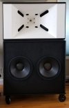
It's meant to be used with a sub.
Despite it having two 18" drivers, the speaker is using them sealed. And being the clean undistorted headroom freak that I am, I decided to use them high passed at 40Hz.
A dual 18" reflex tuned f3 @ 25Hz sits under the speaker.
So the entire speaker is a 6-way.

I never bother measuring subs indoors. I just cross a main and sub together using the sub's outdoor ground plane measurement, with timing based on the known distance to the sub's acoustic center.

s11 cart black crop.jpg
 

OCA

Addicted to Fun and Learning
Forum Donor
Joined
Feb 2, 2020
Messages
679
Likes
499
Location
Germany
Good question.

It's meant to be used with a sub.
Despite it having two 18" drivers, the speaker is using them sealed. And being the clean undistorted headroom freak that I am, I decided to use them high passed at 40Hz.
A dual 18" reflex tuned f3 @ 25Hz sits under the speaker.
So the entire speaker is a 6-way.

I never bother measuring subs indoors. I just cross a main and sub together using the sub's outdoor ground plane measurement, with timing based on the known distance to the sub's acoustic center.

View attachment 334764
Do you have in room measurements (bode plots) of your complete system?
 

gnarly

Major Contributor
Joined
Jun 15, 2021
Messages
1,037
Likes
1,474
Do you have in room measurements (bode plots) of your complete system?

Here's a transfer function of the same single speaker in #76, made at 1m out in the room.
This one has the 18"s in the syn horn reaching down to a little below 30Hz.
It does not include the dual 18" sub under the white horn.

syn11 dcx first tune 1m.JPG


This may sound a little incredible...but having made 10's of thousands of transfer and impulse measurements on DIY speakers over the last decade,
I've never bothered making full-system indoor listening-position measurements.
I've made many in-room measurements for just subs, and trying different sub deployments, but not for mains w/wo subs at LP.
All my main speaker measurements and tunings have been made as quasi-anechoic as possible, preferably outdoors, but sometimes indoors at 1m or so.

After the best quasi-anechoic tuning I can achieve, I live with the system indoors, and let my ears guide me in making acoustic treatments / positioning etc...and using general tone control EQs.
Large horns hold good directivity down low, and their constant directivity I keeps sound off sidewalls.
Everything sounds awesome...So I've never been overly concerned with room-correction.

Ok, all that said...I made my first full-range, main and sub listening position measurements, literally this last week.
Reason being, .bought Dirac Live RCS at the 30% off sale last month. Standalone on PC.
Finally trying some room correction...

Here's just the left side, but does include both main and sub.
Purple is before Dirac, blue after. Used Dirac's tight correction pattern, and let it do its thing 20Hz to 20kHz, just to see how it works for now.

syn11 left dirac try before and after.JPG


The 18"s in the main are high-passed at 40Hz; the 18"s in the sub are low passed at 80Hz. I can see I have a phase issue between them at listening position.
Will fix that.

One cool aside is, I think I've worked out how to make transfer functions of what Dirac is doing electrically.

It appears at quick look, that for a single speaker Dirac essentially performs straight minimum phase magnitude corrections. ( which of course also corrects phase)

When I ran it for 2 speaker stereo, the first speaker again appeared to get only min phase mag corrections, whereas the second speaker got both min phase mag corrections and additional phase only corrections.
Gonna dissect this ...always been a roll my own kinda dude !
 
Last edited:
Top Bottom