• WANTED: Happy members who like to discuss audio and other topics related to our interest. Desire to learn and share knowledge of science required. There are many reviews of audio hardware and expert members to help answer your questions. Click here to have your audio equipment measured for free!

Manually time-aligning subwoofer(s) to mains - how to

dualazmak

Major Contributor
Forum Donor
Joined
Feb 29, 2020
Messages
2,850
Likes
3,047
Location
Ichihara City, Chiba Prefecture, Japan
I shifted the graph to visualise the required delay. Delay can come from filters on the electrical side, but also from the physical driver differences (domes curve out, but cones curve in, so their surfaces are different distances away from the mic).
OK, understood what you mean.

You are presuming that your woofer has no physical delay, but I am suggesting it does.
No,not at all! This is why I always have the time-zero 10 kHz marker which should be "recorded" by tweeter(s) even for WO and or SW measurements.

I strongly request you to first read carefully my post #493 where I clearly objectively found that SW delays in 16.0 msec against my WO+SQ+TW+ST.
(I believe very well fit for the scope of this thread on SW alignments.)

Then in mypost #504, I objectively found that my WO relatively delays 0.3 msec against SQ+TW+ST.

(I dared not to write my post on "there is no delay between SQ, TW, and ST".)

Consequently, my final time-alignment tuning for time-align to the most dalying SW;
0.00 msec (no) group delay for SWs
16.0 msec group delay for WOs
16.3 msec group delay for SQs+TWs+STs

Hope these are well understandable for you.
 
Last edited:

neRok

Senior Member
Joined
Oct 7, 2022
Messages
304
Likes
175
Location
Australia
Then in mypost #504, I objectively found that my WO relatively delays 0.3 msec against SQ+TW+ST.
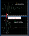
Yes I see how you got 0.3ms, but I think you lined up the wrong peaks because you did not apply the required invert first (required for L-R filters to sum properly).

v to c.png

Edit: To anyone other readers wondering "why are they polluting the sub aligninment thread with driver alignment talk" - well I think it is the exact same problem. It's just measuring and aligning IR's (IR's that are time aligned by acoustic ref).
 
Last edited:

dualazmak

Major Contributor
Forum Donor
Joined
Feb 29, 2020
Messages
2,850
Likes
3,047
Location
Ichihara City, Chiba Prefecture, Japan
Maybe, or may not be, your point would be somewhat valuable.
EDIT: I will soon PM you, since according to your red marker lines, it looks you are saying SQ sound would be delaying against WO which is really strange and odd. Synchronized X-axis is the real-world time clock....

In any way, I have done, therefore and thereafter, my careful "time alignment tuning" between WO and SQ by precisely observing the "WO+SQ" real-world sound with 0.1 msec-step delay settings for SQ sound in the rest of my post #504... ;)

And furthermore and most importantly, thus best tuned total time alignment as well as the best tuned Fq response (ref. my latest setup as of August 3 2023 here), very well fit our (me and my wife, and audio enthu friends) subjective music listening preferences as shared here #520 and here #687.

I really would like to invite you to our listening room, if you would have chance to be in Japan in the near future, for our enjoyable audio listening sessions and discussions (as well as possible further tuning experiments together).:)

If needed, let's keep further communication on my project thread, please.
 
Last edited:

ErLan

Member
Joined
May 16, 2023
Messages
39
Likes
24
Thanks all for this very comprehensive and helpful thread.

I am trying to deploy the methods that are captured in this thread (simple ones as I am not that expert) on my non-treated room 2.1 setup.
I have a separate controls for L+R+Sub (via. Asus Xonar U5 and EqAPO). While the intention is to crossover low frequencies of the L&R speakers to the ".1" channel. The Sub 'raw' signal is generated through adding L+R+LFE and lowpassing (LR4) it on 500Hz.
(so far, quite standard, I know :))
My dilemmas start while trying to match the Sub phase in order to find the delay and operational cross-over range.
  1. As expected from untreated room, the L & R phases are not identical hence matching sub to either yields somewhat different numbers.
    I thought to match sub phase is to L+R phase (either acquired or as vector sum), but not sure whether this average will generate a suboptimal value that too compensate for all
  2. Another practice that was mentioned here is to set sub based on one speaker (e.g. LFE = Rt) match sub only to it speaker (e.g.: Rt) while compensating for the neglection of L through amplification (and faith that it will not impair some of the stereo imaging, as crossing will take place <120Hz)
  3. Last, given the inherent 'artifact' caused by room mode and reflections, what may be the best practice to set crossover value while taking into consideration that the - likely - I will not be able to identify a a range where the Sub &mains have parallel phase slope within crossover +/-10dB.
Attached are REW measurements that may help to demonstrate the complexity.

Many thanks for the yet to come lessons.
 

Attachments

  • ErLan_RtLtSub_alignment experience - ASR.zip
    3.2 MB · Views: 31

ernestcarl

Major Contributor
Joined
Sep 4, 2019
Messages
3,113
Likes
2,330
Location
Canada
Thanks all for this very comprehensive and helpful thread.

I am trying to deploy the methods that are captured in this thread (simple ones as I am not that expert) on my non-treated room 2.1 setup.
I have a separate controls for L+R+Sub (via. Asus Xonar U5 and EqAPO). While the intention is to crossover low frequencies of the L&R speakers to the ".1" channel. The Sub 'raw' signal is generated through adding L+R+LFE and lowpassing (LR4) it on 500Hz.
(so far, quite standard, I know :))
My dilemmas start while trying to match the Sub phase in order to find the delay and operational cross-over range.
  1. As expected from untreated room, the L & R phases are not identical hence matching sub to either yields somewhat different numbers.
    I thought to match sub phase is to L+R phase (either acquired or as vector sum), but not sure whether this average will generate a suboptimal value that too compensate for all
  2. Another practice that was mentioned here is to set sub based on one speaker (e.g. LFE = Rt) match sub only to it speaker (e.g.: Rt) while compensating for the neglection of L through amplification (and faith that it will not impair some of the stereo imaging, as crossing will take place <120Hz)
  3. Last, given the inherent 'artifact' caused by room mode and reflections, what may be the best practice to set crossover value while taking into consideration that the - likely - I will not be able to identify a a range where the Sub &mains have parallel phase slope within crossover +/-10dB.
Attached are REW measurements that may help to demonstrate the complexity.

Many thanks for the yet to come lessons.

There is a small difference in the time between left and right channels where the right speaker is off by about +3 inches. No big deal, and I adjusted it by adding a 0.260 time offset to the right channel manually.

1700251907032.jpeg 1700251916468.jpeg

The Sub 'raw' signal is generated through adding L+R+LFE and lowpassing (LR4) it on 500Hz.

1700253242952.jpeg
*after applying delays, check by inverting the polarity as well to see what yields the best summed response

BTW, I don't think that is "standard". I assume you want to copy the left and right signals into the sub channel. For that, you would need to apply a low pass filter as well, say, 120 Hz. The LFE is usually run full-range and it is band-limited naturally by the sub's own frequency response. However, in order for the bass managed left and right sub signals to not partially cancel out digitally/electronically with the LFE's own full range signal, an all pass filter and/or delay needs to be applied to itself prior summing with the L+R low passed signals. An easy way to avoid this issue is by using the same low pass filter for the LFE and copied left and right signals e.g. 500 Hz LPF you mentioned.

IMO, though, 500 Hz is too high. Maybe try 200 Hz instead.

Presumably, measuring the LFE channel would yield +10dB hotter signal. You could either just deduct that from the measurement or boost the mains by 10dB if you want to simulate in REW the aligned sum response of the BM sub signal and mains.


Before summing the sub and mains, you might also want to apply a "standard" high pass, say ~80 Hz maybe, to the mains as well. But that is totally up to you.
 

ernestcarl

Major Contributor
Joined
Sep 4, 2019
Messages
3,113
Likes
2,330
Location
Canada
Just to be clear, I do not use Equalizer APO... rather only JRiver.

One more thing I recall when copying left and right etc. to the sub channel. Since it is also assigned as the .1 LFE channel as well, if one were doing things totally manually, -10 dB needs to applied to each mains copied signal prior summing with the sub-LFE channel:

1700255429839.jpeg


U1 is just a temp place holder variable before summing.
 

ErLan

Member
Joined
May 16, 2023
Messages
39
Likes
24
Well...
I deployed the propsed changes inLFE calculations, as well as tested HPF on my mains (on top of natural 80-100Hz@12dBHPF).
Yet, when coming to calculate the delay I realized the high sensitivity of this parameter to FDW value (FDW 5: 5msec, no FDW: 25msec). So now I am puzzled :)
Any tips/guidence will be highly appreciated.
 

ernestcarl

Major Contributor
Joined
Sep 4, 2019
Messages
3,113
Likes
2,330
Location
Canada
Well...
I deployed the propsed changes inLFE calculations, as well as tested HPF on my mains (on top of natural 80-100Hz@12dBHPF).
Yet, when coming to calculate the delay I realized the high sensitivity of this parameter to FDW value (FDW 5: 5msec, no FDW: 25msec). So now I am puzzled :)
Any tips/guidence will be highly appreciated.

Might be easier to show us with your measurements. FDW for low frequencies is not normally something that I use by default.
 

ErLan

Member
Joined
May 16, 2023
Messages
39
Likes
24
Thanks @ernestcarl
Attached are '2 samples'.
  • ASR01: Capture Lt, Rt, Sub where Lt and Rt are positioned ~nearField (2m) relative to main listening position - best 'sound experience so far but deep into living room for critical listening, and return back when done)
  • ASR02: Capture Lt, Rt, Sub where Lt and Rt are position ~midField (?) (3m) relative to main listening position - a compensation with living room constraints.
In both measurement sub is on the same position, close as possible to front wall and ~0.25Width form right wall (best measurements while taking into account inherent living room constraints).

I hoped that near field measurement will bring some more consistency to the phase (more direct sound, less prone to room reflection), nevertheless, In both positions:

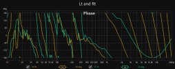
  1. alignment of SUB to Lt+Rt is sensitive to FDW; where, based on phase: (a) no FDW I get delay of ~25-30msec, (b) FDW = 5: delay jumps down to 3-5msec.
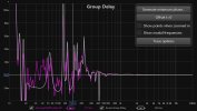
  2. If I interpret it correctly, when looking at the GD of the combined Lt+Sub and/or Rt+Sub measurement (see ASR02), it seems like that when using the delay based on non-FDW measurements, the bass is ~20msec too early, means the FDW based value is more accurate(?); also pointing out on excessive peaks which are likely related to room mode or reflection.
Last, worth to mention (again) that this is a standard living room, hence sofas, TV on front wall - yet no wall treatment.
hope it clarifies.
 

Attachments

  • ErLan_RtLtSub_alignment experience - ASR_01.zip
    3.2 MB · Views: 20
  • ErLan_RtLtSub_alignment experience - ASR_02.zip
    4.4 MB · Views: 20

ernestcarl

Major Contributor
Joined
Sep 4, 2019
Messages
3,113
Likes
2,330
Location
Canada
Thanks @ernestcarl
Attached are '2 samples'.
  • ASR01: Capture Lt, Rt, Sub where Lt and Rt are positioned ~nearField (2m) relative to main listening position - best 'sound experience so far but deep into living room for critical listening, and return back when done)
  • ASR02: Capture Lt, Rt, Sub where Lt and Rt are position ~midField (?) (3m) relative to main listening position - a compensation with living room constraints.
In both measurement sub is on the same position, close as possible to front wall and ~0.25Width form right wall (best measurements while taking into account inherent living room constraints).

I hoped that near field measurement will bring some more consistency to the phase (more direct sound, less prone to room reflection), nevertheless, In both positions:

  1. alignment of SUB to Lt+Rt is sensitive to FDW; where, based on phase: (a) no FDW I get delay of ~25-30msec, (b) FDW = 5: delay jumps down to 3-5msec.
  2. If I interpret it correctly, when looking at the GD of the combined Lt+Sub and/or Rt+Sub measurement (see ASR02), it seems like that when using the delay based on non-FDW measurements, the bass is ~20msec too early, means the FDW based value is more accurate(?); also pointing out on excessive peaks which are likely related to room mode or reflection.
Last, worth to mention (again) that this is a standard living room, hence sofas, TV on front wall - yet no wall treatment.
hope it clarifies.

Vector average of EQAPO_Sub+Left and Right

1701063462265.jpeg 1701063476586.jpeg 1701063481622.jpeg 1701063485583.jpeg

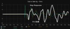
Your sub is playing too early as seen above which very likely would significantly psychoacoustically reduce midrange clarity.


My own suggestion would still be very similar to what I mentioned before: 200Hz LPF (BU24dB/oct) on sub and delay ~-4.8 ms (+4.8 ms applied to mains) while inverting polarity, 80 Hz HPF (BU24dB/oct) on mains. Feel free to try other combinations like 120 Hz L-R 24dB/oct etc.

I arbitrarily reduced the sub SPL by -10 dB in the ff. quick example summed simulation:

1701064798194.jpeg 1701064805422.jpeg 1701065258297.jpeg 1701064950920.jpeg
*delay and polarity was set manually by eyeballing individual IR and summed response


Personally, I'd rather have the sub a bit late (40ms peak energy time which is still acceptable) than having the sub start too early. Of course, you should perform your own listening tests to determine what is audibly better sounding.
 

Attachments

  • erlan quick test.zip
    1.4 MB · Views: 18
Last edited:

ErLan

Member
Joined
May 16, 2023
Messages
39
Likes
24
@ernestcarl many thanks!
(As always) very insightful information.
So, to recap my takeaways,

(1) I should align the timing based on the IR start ('snake head' as mention in one of the clips) of the Sub to the Lt+Rt (vector sum), rather than aligning the sub peak to the Rt+Lt peak (e.g. via spectrograph).

(2) While thus may lead to some delays in the sub peak relative to the main Rt & Lt - this is psycho acoustically preferable.

(3) Probably (based on other threads) FIR may help to 'streighten' abit the sub curved profile - yet this shpuld be carefully assessed due to pre-ringing affects.

Did I get it right?
 

ernestcarl

Major Contributor
Joined
Sep 4, 2019
Messages
3,113
Likes
2,330
Location
Canada
(1) I should align the timing based on the IR start ('snake head' as mention in one of the clips) of the Sub to the Lt+Rt (vector sum), rather than aligning the sub peak to the Rt+Lt peak (e.g. via spectrograph).

IR/step and phase should be close to each other and not drift too far apart. As well as aim for a summed magnitude response that does not have so much of a huge dip/cancellation around the crossover.

(2) While thus may lead to some delays in the sub peak relative to the main Rt & Lt - this is psycho acoustically preferable.

The reality is, your in-room IR and phase below 200 Hz is kinda messy, so there really isn't a super clear-cut "best xo EQ and delay" setting that I can give. There are multiple possible combination of settings that would work fine...

(3) Probably (based on other threads) FIR may help to 'streighten' abit the sub curved profile - yet this shpuld be carefully assessed due to pre-ringing affects.

Yes, FIR filtering after-the-fact can improve the time domain performance a little bit. However, this will increase setup complexity and potentially cause other issues such as audible bass pre-delay and signficant lip-sync delay.


Below is an example xo and EQ correction of your right channel only with 683ms FIR delay (65k tap and 48k sample rate):

1701075406695.png 1701075409841.png 1701075412895.png 1701075415682.png 1701075418825.png 1701075422146.png
 

Attachments

  • erlan Rt channel EQ.zip
    4.2 MB · Views: 24

ErLan

Member
Joined
May 16, 2023
Messages
39
Likes
24
Wow... looks very impressive!
I guess that it need to go through so.e listening tests that will assess its pre-ringing et al.
Seems like I am only in the start of my journey ;)
(Many thanks)
 

ninetylol

Addicted to Fun and Learning
Joined
Dec 7, 2019
Messages
689
Likes
652
Can someone do a failproof step for step guide? I dont understand a lot of what is said in post#1 and my graphs Look totally different.

So i should do 2 different measurements:

1. one low passed sub only (30-150hz)

or whole system just 30-150hz?

2. another only high passed Mains

or full system (highpassed mains + low passed sub?) 10-20khz

I feel really dumb but for me its not clear at all from the guide in first post.
 

Foly83

New Member
Joined
Apr 23, 2021
Messages
3
Likes
1
Hello Ninetylol
You should take two measurements and set the frequency range in the REW to measure
Front left 20-150 Hz without Xo
Subwoofer 20-150 Hz without Xo
The whole thing with time ref and 2M sweep length
Were you used to edit the XO? AVR, mini DSP?
You are welcome to provide your measurements here.
This way we can help you better.
Maybe more people will help you.

best regards Alex
 

ninetylol

Addicted to Fun and Learning
Joined
Dec 7, 2019
Messages
689
Likes
652
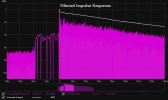
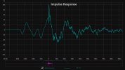
Okay I did what you said and sadly my impulse and step response looks really wonky so i cant work with it.
Screenshot 2024-04-16 163008.png


Screenshot 2024-04-16 163016.png


I came up with a different strategy though.
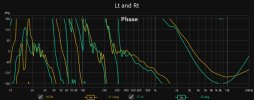
1. I used the measurements with FDW applied and looked at the phase responses of the sub itself and the speaker.
2. Then I added delay to the speakers and measured the xo-ed whole system (sub + speaker both low and high passed).
3. I added delay and looked when the phase response looked as close as the phase of only the sub. For me this was 5,5ms

Screenshot 2024-04-16 163933.png


Since my sub is about 1m farther from ears than the speakers (+ possible processing delay) this value doesnt sound too wrong.

Dont know if this is the right procedure but to my ears it sounds good.
 

terryforsythe

Senior Member
Forum Donor
Joined
May 4, 2022
Messages
489
Likes
513
Dont know if this is the right procedure but to my ears it sounds good.
That is the most important measurement.

Another test you can try to see how close you have it is to generate a tone at the crossover frequency. Measure the SPL at the listening position and adjust the time delay until you find the delay that produces the highest SPL at the crossover frequency. This will get you very close. For this I use the "Generator" and "SPL meter" in REW.

After that, run a frequency response sweep. If the frequency response through the crossover region is smooth, you are set. If you see a significant dip immediately below or above the crossover frequency, try making small adjustments to the time delay to see if they correct the dip. Depending on how quickly the group delay of the speakers and subwoofer diverge above or below the crossover frequency, you may need to find a setting that provides the best balance across the entire crossover region.

With my setup, I got the best crossover transition by plugging my speaker ports in order to lower the group delay of my speakers in the bass region.
 
Last edited:

Foly83

New Member
Joined
Apr 23, 2021
Messages
3
Likes
1
Please upload your mdat.
If you want, two measurements with the desired Xo
Of course everything with time ref
 
Last edited:

ninetylol

Addicted to Fun and Learning
Joined
Dec 7, 2019
Messages
689
Likes
652
Please upload your mdat.
If you want, two measurements with the desired Xo
Of course everything with time ref
heres the measurements i did. I set the crossover to x85 24db/octave in Equalizerapo

first two measurements no crossover is active
 

Attachments

  • sub sync.zip
    2.9 MB · Views: 4
Top Bottom