• WANTED: Happy members who like to discuss audio and other topics related to our interest. Desire to learn and share knowledge of science required. There are many reviews of audio hardware and expert members to help answer your questions. Click here to have your audio equipment measured for free!

Manually time-aligning subwoofer(s) to mains - how to

Daverz

Major Contributor
Joined
Mar 17, 2019
Messages
1,309
Likes
1,476
I think I found an easier method for finding the main speaker delay based on Mitchco's method of time aligning drivers in the context of Acourate.

Since the subwoofer impulse peak usually falls after the main peak and is very low in amplitude, it gets lost in the noise following the main peak. The idea is to set an initial delay for the main speaker impulse peak so that the subwoofer impulse peak falls in the "quiet" part of the whole impulse response well before the main peak so that we can see it.

Simply set an initial large delay for your main speakers in your bass management hardware or software, something that will be several times larger than the subwoofer delay, and then measure the sub + main system with REW using a timing reference. REW should put the main speaker impulse peak at 0 seconds. The subwoofer impulse peak should, hopefully, be well before the main impulse peak but at a very low level. In the impulse response tab, set your left limit to a negative number at least as large as the delay (e.g. -0.050 seconds) and your right limit to 0.0. Set your vertical limits to something small like -0.3% to 0.3%. Hopefully you should see the maximum peak (or minimum trough if polarity is inverted.) If you can't find a peak, you may need to increase the delay.

Eyeball the subwoofer impulse peak and set the cursor there, then read off the time at the cursor position. The correct delay is then your initial delay plus the time of the subwoofer peak. In my case, I set an initial delay of 30 ms, and I found the subwoofer impulse peak at -10.8 ms, so my mains delay is 19.2 ms.

subwoofer-impulse.jpg
 
Last edited:

Daverz

Major Contributor
Joined
Mar 17, 2019
Messages
1,309
Likes
1,476

Now I'm not so sure. I did some more tests today delaying the mains by 40 ms and 100 ms:

mains_delays.jpg


Now another higher peak is revealed and taking that as the subwoofer impulse peak would make the subwoofer delay over 30 ms, which is hard to swallow. I'm not sure where so much delay would be in my system. The subwoofer is an SVS SB-1000 Pro, which does have some delay due to the built-in DSP. The DAC is a Motu M4 with the mains on balanced connections and the sub on unbalanced connections. Crossover is at 80 Hz and filters are Linkwitz-Riley 8th order filters applied by CamillaDSP.

EDIT: I suppose the big peak may just be the confusing reflections mentioned by the OP.
 
Last edited:

dualazmak

Major Contributor
Forum Donor
Joined
Feb 29, 2020
Messages
2,854
Likes
3,063
Location
Ichihara City, Chiba Prefecture, Japan
Although quite belated, I just noticed this thread.

I recently established 1 msec and 0.1 msec precision time alignment among all the SP drivers (sub-woofers, woofers, squawkers, tweeters and super-tweeters) in my multichannel multi-driver multi-way multi-amplifier stereo system using rather primitive but reliable reproducible measurement methods.

If you would be interested, please find the details on my project thread;

- Precision measurement and adjustment of time alignment for speaker (SP) units: Part-1_ Precision pulse wave matching method: #493
- Precision measurement and adjustment of time alignment for speaker (SP) units: Part-2_ Energy peak matching method: #494
- Precision measurement and adjustment of time alignment for speaker (SP) units: Part-3_ Precision single sine wave matching method in 0.1 msec accuracy: #504, #507
- Perfect (0.1 msec precision) time alignment of all the SP drivers greatly contributes to amazing disappearance of SPs, tightness and cleanliness of the sound, and superior 3D sound stage: #520

You may also find my latest system setup here (post #540) on the project thread.
 

RayDunzl

Grand Contributor
Central Scrutinizer
Joined
Mar 9, 2016
Messages
13,250
Likes
17,200
Location
Riverview FL
Alignment...

Once upon a time, I created a sine bass wave in Audacity, and edited a single sample at several bass peaks to give a "tick".

The sine would be played by the sub/woofer, the tick by the treble/tweeter.

index.php


Then record the speaker output and observe the time relationship of the bass peak to the "tick" that should come at the peak of the bass wave.

I found the bass to be 2ms early at 30Hz (or the treble 2ms late) at the listening position, so, not enough to matter, as it would likely change with frequency, and the above was enough to prove the idea worked (to my satisfaction).

Tell the bass player to step back two feet, if it is live and the alignment is not to your fancy...

The tick on the negative side is a reflection from somewhere, probably the wall behind the dipole speakers.
 

MaxRockbin

Active Member
Joined
May 26, 2021
Messages
109
Likes
131
Location
Portland, Oregon
Alignment...

Once upon a time, I created a sine bass wave in Audacity, and edited a single sample at several bass peaks to give a "tick".

The sine would be played by the sub/woofer, the tick by the treble/tweeter.

index.php


Then record the speaker output and observe the time relationship of the bass peak to the "tick" that should come at the peak of the bass wave.

I found the bass to be 2ms early at 30Hz (or the treble 2ms late) at the listening position, so, not enough to matter, as it would likely change with frequency, and the above was enough to prove the idea worked (to my satisfaction).

Tell the bass player to step back two feet, if it is live and the alignment is not to your fancy...

The tick on the negative side is a reflection from somewhere, probably the wall behind the dipole speakers.
Nice experiment!
 

takechan

New Member
Joined
May 28, 2023
Messages
2
Likes
1
Hi,

I'm having difficulty aligning my main speakers / center to my sub. The sub is located next to the 'R' speaker. The phase and 80 Hz filtered IR doesn't seem "too bad", but if I try the alignment tool at 80 Hz with my 'R' speaker it's waaay off.

Could someone have a look? I've attached the measurements using 1M sweeps with acoustic reference 'L'.

Best regards,

Peter
 

Attachments

  • Alignment tool.png
    Alignment tool.png
    458 KB · Views: 84
  • Filtered IR.png
    Filtered IR.png
    609.1 KB · Views: 97
  • Phase.png
    Phase.png
    251.7 KB · Views: 78
  • 2023-05-28 Phase adjustment Filtered IR 80 Hz v2.zip
    505.5 KB · Views: 39

dualazmak

Major Contributor
Forum Donor
Joined
Feb 29, 2020
Messages
2,854
Likes
3,063
Location
Ichihara City, Chiba Prefecture, Japan
I'm having difficulty aligning my main speakers / center to my sub.

Just for your possible interest and reference, I did rather intensive measurements and tuning of "time alignment" on my PC-DSP-based multichannel mutli-SP-driver multi-amplifier fully active stereo audio setup, using primitive but well validated accurate DIY methods; my efforts were/are shared on my project thread.

- Precision measurement and adjustment of time alignment for speaker (SP) units: Part-1_ Precision pulse wave matching method: #493
- Precision measurement and adjustment of time alignment for speaker (SP) units: Part-2_ Energy peak matching method: #494
- Precision measurement and adjustment of time alignment for speaker (SP) units: Part-3_ Precision single sine wave matching method in 0.1 msec accuracy: #504, #507
- Measurement of transient characteristics of Yamaha 30 cm woofer JA-3058 in sealed cabinet and Yamaha active sub-woofer YST-SW1000: #495, #497, #503, #507
- Identification of sound reflecting plane/wall by strong excitation of SP unit and room acoustics: #498
- Perfect (0.1 msec precision) time alignment of all the SP drivers greatly contributes to amazing disappearance of SPs, tightness and cleanliness of the sound, and superior 3D sound stage: #520

If you would be seriously interested in the precision tone burst signals (test tones) I prepared for these measurements, simply PM me writing your wish.

These methods also can be applied in DSP-based single-DAC single-Amp LCR-network passive multi-SP-driver system as I illustrated in my post here.
 

takechan

New Member
Joined
May 28, 2023
Messages
2
Likes
1
Just for your possible interest and reference, I did rather intensive measurements and tuning of "time alignment" on my PC-DSP-based multichannel mutli-SP-driver multi-amplifier fully active stereo audio setup, using primitive but well validated accurate DIY methods; my efforts were/are shared on my project thread.

- Precision measurement and adjustment of time alignment for speaker (SP) units: Part-1_ Precision pulse wave matching method: #493
- Precision measurement and adjustment of time alignment for speaker (SP) units: Part-2_ Energy peak matching method: #494
- Precision measurement and adjustment of time alignment for speaker (SP) units: Part-3_ Precision single sine wave matching method in 0.1 msec accuracy: #504, #507
- Measurement of transient characteristics of Yamaha 30 cm woofer JA-3058 in sealed cabinet and Yamaha active sub-woofer YST-SW1000: #495, #497, #503, #507
- Identification of sound reflecting plane/wall by strong excitation of SP unit and room acoustics: #498
- Perfect (0.1 msec precision) time alignment of all the SP drivers greatly contributes to amazing disappearance of SPs, tightness and cleanliness of the sound, and superior 3D sound stage: #520

If you would be seriously interested in the precision tone burst signals (test tones) I prepared for these measurements, simply PM me writing your wish.

These methods also can be applied in DSP-based single-DAC single-Amp LCR-network passive multi-SP-driver system as I illustrated in my post here.
Hi dualazmak,

Thanks - that seems very in-depth, advanced, and thorough!

I was kinda hoping to replicate the method from this thread, but I'll give it a read!
 

mrlawng9

Member
Joined
Jan 7, 2020
Messages
25
Likes
11
Props to OP and all the subsequent contributors to this thread. I've scoured the internet for years and have absorbed just about everything on this topic. From my perspective, this thread is by far the most useful and educational. I've been referring to it for several years now and think it is hitting on one of the most important and elusive parts of proper audio setup.

At the same time, I also still struggle to effectively align multiple subs to mains. This thread gets so close but to no fault of anyone, multiple similar-but-slightly-different methodologies are discussed and a definitive (from a layperson's perspective) step by step procedure that addresses some of the gaps I (and possibly others) struggle with, to my knowledge, does not exist.

For example, I'm confused about the following:
  • Level matching procedures for subs and mains - it would be amazing if the experts on this forum could help us understand not just how to properly level-match subs and mains for phase alignment but also shed some context on what happens when we have to increase levels after this procedure (e.g. to increase sub amplitude ~10db to) dial in the Harman curve or house curve of choice. What happens to phase-alignment as amplitudes change and crossovers are implemented?
  • Left and Right Mains Delays - Every system I have access to has deltas between crossovers acoustically. For example, when I set up a system with multiple subwoofers, I typically get slight variations at the crossover (e.g. 52hz and 56hz when implementing a 50hz crossover). Do the left and right crossovers have to be identical acoustically for this to work? When I follow the procedures in this thread I wind up with separate delay settings for each main speaker. They sum nicely when I measure Left main (or right main) plus my dual mono subs but when both mains and subs are on I'm unable to get a solid image coming from between the speakers. When I use one of the values I've derived in both speakers, it sounds better, but still wonky. I'm sure I've missed something simple here but my point is that while this thread has helped me immensely, I still could use a little help connecting all of the dots!
Just a couple of example areas where I get stuck. And, I sincerely hope this is not perceived as a rant or an attack! I'm so appreciative of everyone's comments and contributions.

If anyone is willing to leverage their expertise to write a guide on how to level-match and phase-align multiple subwoofers to mains from the perspective that an enthusiast will start from scratch and be applying crossovers, EQ, delays, etc..., I would be incredibly appreciative and I get a feeling that the community would benefit tremendously from it.

Thank you :)
 

neRok

Senior Member
Joined
Oct 7, 2022
Messages
304
Likes
175
Location
Australia
Interesting thread. I see many similarities to what I've been experimenting with in the VBA thread, albeit with different objectives. The video from JBL Pro posted early in the thread was very informative and confirms many things I'd been noticing. Most important is the need to understand that the IR describes all frequencies, and this means it's not proper to align IR's of different measurement ranges by the first peak. Depending upon the capabilities of the DSP and the measuring systems you may have to measure/adjust with certain filters in place, but if you have REW and full control then you may as well measure the "full response". Then you should add filters to the responses so that you are aligning "like for like", and the means in REW you should align the "Filtered IR" with filters like x-over applied (because it can cause ringing that causes phase shifts).

As far as I understand it, it all comes down to the "summed phase". I still don't understand the ramifications with regards to the "magnitude of the system transfer function", aka the SPL reported in REW, as I've been informed of in my "REW is a liar sometimes" thread, but I'm working on that. But I'll explain what I see with happening with the phase by answering this question;

What happens to phase-alignment as amplitudes change and crossovers are implemented?
So there's 2 causes of phase shift I see in the bass range (that's all I'm talking about, the omnidirectional bass range). First is the inherent phase of the speaker/sub, which includes passive/active/DSP x-over and ports (or not), etc. Those things add together and you get what you get, and presumably that is increasing group delay as the frequency gets lower. If you design a ported sub in the likes of WinISD, you will see the group delay increase as the frequency lowers. And if you add low or high pass, it gets worse. But at the same time, it gets worse at a particular rate, and it doesn't have "ups and downs", more like "ups and more ups". And maybe I'm wrong, but this is probably because filters were analogue (electrical components dealing with electrical signals), yet they can be described by maths, which is how DSP applies the same affects. So I don't know if it's possible for a speaker in the bass range to have a blip of decreasing group delay, because that would imply the speaker starts outputting a tone before the tone even exists in earnest the electrical domain. Because think about it, say the current sample is 0dB of a frequency, and the next sample in the source is the natural "+1 sample of a sine wave", but you want 90° phase shift, so "-1 sample of a cosine wave" - how can that happen? So I don't think it can, and that means analogue style filters can only delay. Anyway, that's not super important, only it means if I'm wrong that there's more possibility for corrections.

So if the phase coming out is "the phase", then that means the "direct wave" has that group delay (it's an omnidirectional wave, but the direct line/portion-of-wave will reach you first, so it must be correct (unless there is considerable noise)). And the direct wave must be in the IR, because nothing can arrive faster than it(?-wavelet/wave-packet stuff, their effect=dunno). So you might consider aligning the direct waves, which is akin to the simple distance calculation method. That would be better than nothing, but it doesn't consider what happens next with the reflections. And it seems in the bass range that the reflections (room) dominates, and the boffins have already labelled the phenomenon as the Schroeder frequency.

I think it's good to consider the alternative at this moment - that you and your sub are on a massive plain, so there no reflections besides the ground. I can't imagine it would matter if the speaker is straight ahead or at some equal distance but different angle either side, because in this situation the "direct wave" will arrive when it arrives, and that's "the phase". Anything else must be the room = the reflecting surfaces.

So at every moment soon after the direct wave, all sorts of reflections start arriving at your listening/measuring position[=LP]. There's a period where only "1st reflections" can arrive, but when you consider the geometry of any room VS the time of a single bass note, eventually all sorts of reflections will be arriving at the same time and within 1 cycle. And what-you-hear/what-the-mic measures is the sum of all these reflections. The rooms properties (ie treatment) dictate how powerful these reflections are, but without treatment specifically targeting the bass range (panels with ~100mm of insulation is not enough), chances are they powerful. And so reflections quickly enter a period when so many different ones are happening at the same time, and because they've travelled different distances and maybe even reflected different amount of times, so they have different amplitudes and phase - BUT STILL THEY CAN ADD UP TO BE LOUDER THE DIRECT WAVE. So the end result is, reflection=n has dB=nY with phase=nZ, and they all get added up, and that's what the mic/IR has captured - the sum (the "system transfer function").

So in regards to the quoted question, you can see in the following example that I've made in Audacity where I've added 2 waves together that have the same delay but different amplitude, and it means the resulting wave has a different "summed phase".
phase shift.jpg
If those were waves from the same source, they will sum together at the LP, and you would only see the result (1 speakers STF). But if you're trying to align multiple sources, you need to consider that amplitude change of 1 device can cause phase shift on what is heard (STF1 + STF2 = STF3, which means anything could happen).

And at this point it's taken me way too long to write this much and I can't continue in depth today, so I'll be brief. So if you follow this train of thought you will see that at some frequencies a singular sources "peak energy" moment may be well after its direct wave (because of many constructively overlapping reflections), BUT THIS MIGHT HAVE PHASE SHIFT, and also each source might have vastly different IR's because of their in room position. When you add them together, ANYTHING CAN HAPPEN (because of the different relative phases). If you add peak to peak (energy moments), yer that might be decent, but did you consider specifically having some phase shift, and maybe that phase shift makes the "early waves" stronger and the decay weaker? What if the "magnitude" of the sum is worse, but the early waves are stronger and later waves weaker, is that really worse? Because what if you have so much overhead in your subs you can just brute force correct the "magnitude"? I have examples - tomorrow. Because also, the "magnitude" is doing my head in. Every "wave" on a filtered IR can be weaker, but the "magnitude" is the same, I've "seen it" (in REW). Maybe it's because of phase shift in the IR, which is there. But then I take a Dirac pulse and do a Filtered IR on it, and I don't understand what's happening lol (it's like +30dB on the IR for the same "magnitude").

Actually I want to comment on this post that's been bugging me;
Impulse:
Impulse.jpg


Phase:

Phase.jpg
You can untick (turn off) particular measurements, and then push "+360" on the others. It's arbitrary in a way, because the true difference is in the "group delay". But if you did this, you would have noticed that your "peak energy moments" are ~180° out of phase (180 + a minor delay).

it would be amazing if the experts on this forum could help us understand
Going to add 1 more comment to this: There certainly seems to be some experts of the science side here, but their "attention" seems limited. It's probable that we are "debating" such basic aspects of their profession that they just no longer have the will to reply. Maybe there is more and more knowledge required to solve these problems, and if they properly explained it to us we would be half way to a degree. So at the same time, I'm coming around to the idea of some like DL-ART works as described, it's probably worth spending the money (if you don't want to or can't do room treatments that fix the bass).
 
Last edited:

dualazmak

Major Contributor
Forum Donor
Joined
Feb 29, 2020
Messages
2,854
Likes
3,063
Location
Ichihara City, Chiba Prefecture, Japan
If anyone is willing to leverage their expertise to write a guide on how to level-match and phase-align multiple subwoofers to mains from the perspective that an enthusiast will start from scratch and be applying crossovers, EQ, delays, etc..., I would be incredibly appreciative and I get a feeling that the community would benefit tremendously from it.

Really interesting and important point you are raising, I assume.

I am very sorry, however, I myself would not be properly (or never well) responding to your inquiry, and I feel there would be no single solution nor single "golden gate"...;)

In my DSP-based multichannel multi-SP-Driver multi-amplifier fully active stereo audio project (please find here the latest setup as on August 3 2023), I have independent L&R sub-woofers (SWs), L&R woofers (WOs), Be(Beryllium)-midrange-squawkers (SQs), Be-dome-tweeters (TWs), and metal-horn-super-tweeters (STs); actually 5-way 10-Ch system/setup, where of course I can control all of the 10-Ch gains and delays (phases) independently using DSP as well as in multichannel DAC unit (DAC8PRO), also in analog level using each of the integrated-amps; the active SW also has its own volume, low-pass crossover and phase-reverse switch.

At least based on my limited (but intensive) experiments and experiences, my present "personal best suggestion" as of today would be to use suitably prepared (and well QC-ed) 
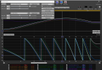
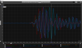
8-wave, 3-wave, 1-wave "sine pulse tone bust test signals" of various Fq for room air-sound recording using single measurement microphone at your listening position, and to analyze the recorded room air sound by using Adobe Audition's time-amplitude spectrum and more importantly 3D-color spectrum representing time-gain-Fq in one diagram hopefully using independent separate PC (or MAC); you may/should also "record" the same test tone signal in digital-level and/or analog-line-level for comparative analysis with the recorded room air sound.

One of the wonderful pros of this approach is that, using DSP's flexible "mute" and "play" buttons for each channel (or using each of the integrated amps), we can play-and-record any of the single, and any combination of, all the channels available (in my case L&R total 10-Ch).

As you may easily guess, we have almost infinity number of combinations; e.g. even if limited only to SW and WO, L-SW only, R-SW only, L-WO only, R-WO only, L-SW + R-SW, L-WO +R-WO, L-SW + L-WO, R-SW + R-WO, L-SW + L-WO + R-SW + R-WO, etc., etc.

Recordings and measurements of the test tone sound in L-only R-only and L+R are always needed since our home listening room is never to be anechoic and never to be physically symmetrical L-to-R and Up-to-Down.

The selection of Fq for the tone burst sine wave (8-, 3,- 1-wave) signals would be also critical depending on your SP drivers and your XO Fq/slope. Whatever the two filter slopes at XO Fq would be, we have more or less Fq zone where both of the XO-ed two SP drivers sing together, and therefore the recording and measurement/analysis at "XO Fq" and "around (lower and higher) XO fq" would be critical for better-to-best tuning of "gain and phase (time alignment)" matching/tuning.

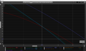
By very carefully observing/analyzing such 2D-gain-time-spectrum and 3D-color-spectrum which give you not only "recorded air sound wave shapes" of the test tone but also "sound energy distribution" (a kind of my terminology) in 3D (time-gain-Fq) space, we can get very much useful invaluable information for better-best tuning of gain matching, selection of XO Fq, selection of XO slopes, as well as phase/delay/time-alignment. Please find here and here two of simple but the best typical example cases for what I mean.

As you know well, however, all of gain, XO Fq, XO slopes, delay/phase/time-alignment are not fully independent, and all of them are more-or-less interdependent with each other. Consequently, we need to find acceptable better-best "compromised combination" of these parameters in our own audio setup in our actual home room environment.

I actually did such recording and analysis so many times with various combinations of my excellent singers (SP drivers) and DSP parameters, and I shared only the limited essence of my approach on my project thread as follows;

- Precision measurement and adjustment of time alignment for speaker (SP) units: Part-1_ Precision pulse wave matching method: #493
- Precision measurement and adjustment of time alignment for speaker (SP) units: Part-2_ Energy peak matching method: #494
- Precision measurement and adjustment of time alignment for speaker (SP) units: Part-3_ Precision single sine wave matching method in 0.1 msec accuracy:
#504, #507
- Measurement of transient characteristics of Yamaha 30 cm woofer JA-3058 in sealed cabinet and Yamaha active sub-woofer YST-SW1000: #495, #497, #503, #507
- Identification of sound reflecting plane/wall by strong excitation of SP unit and room acoustics: #498

EDIT: Through these primitive but easy-to-understand straightforward measurements/tunings, you can gradually accumulate your understandings/insights on what would be the internal (rather black-box?) automatic procedures in advanced DSP/tuning software such as REW and EqualizerAPO. You would please note that such advanced software would not always gives you proper/correct tuning information as @zergxia kindly shared here on my project thread.

Of course our room does greatly "matter" for our audio sound quality; just for example,
- Not only the precision (0.1 msec level) time alignment over all the SP drivers but also SP facing directions and sound-deadening space behind the SPs plus behind our listening position would be critically important for effective (perfect?) disappearance of speakers: #687


Furthermore, you (we) always should not over-trust objective measurements and tuning; for the final decision on any of our tuning goals, we should trust our ears and brain based on your hearing and music preferences. This is also very important in measuring/tuning/deciding your best Fq response "house curve" all throughout 20 Hz to 22 kHz (ref. recent valuable discussions on this thread; post #419 and thereafter). And hopefully you would better to implement flexible on-the-fly relative gain (tone) control mechanisms for your "Fq response housecurve(s)", just I have done in my project.

In this context, I believe it is very important having your/our own preferable and consistent "audio reference/sampler music playlist and the intact music tracks thereof" throughout your audio exploration and tuning. Please refer to my summary post here and here for my own "audio reference/sampler music playlist".

If you would be seriously interested in the test tone signals I prepared for my measurement/tuning, and/or intact tracks of my "audio sampler reference/sampler playlist", I would be more than happy sharing them personally with you. If this would be the case, please simply PM me writing your wish.
 
Last edited:

mrlawng9

Member
Joined
Jan 7, 2020
Messages
25
Likes
11
Many thanks @neRok and @dualazmak. Really appreciate your contributions / responses. There is a LOT for me to chew on with both of your posts. I look forward to absorbing them and learning from both of you.
 

ernestcarl

Major Contributor
Joined
Sep 4, 2019
Messages
3,113
Likes
2,330
Location
Canada
What happens to phase-alignment as amplitudes change and crossovers are implemented?

You can simulate this in REW, Smaart etc. or see it in real time with RTA... if the phases aren't matched too well between speakers/channels around the xo range you will get unexpected unevenness in the summed amplitude/magnitude response as the levels change e.g. increasing bass managed subwoofer and/or LFE output levels when played at same time with mains.
1693261537210.png 1693261543453.png 1693261553678.png 1693261557587.png 1693261560743.png


If your summed bass managed left and right speakers measure/sound worse, then their timing and/or phases may be deviating by a considerable amount. This can also be observed by overlaying the measurements of interest e.g. left, right, and sub channels.

You can use the IR graphs to check for the relative "time of flight" and arrivals between speakers as measured at the microphone/MLP if a proper time reference is set up; otherwise, magnitude and phase is all you need, and probably some frequency dependent windowing and/or gating to clear out some of the "pollution" from the room itself.

1693262971214.png 1693262977835.png

Occasionally, pre-equalization is necessary to get a clearer view of how much to adjust the output levels e.g. sub FR is too crooked when played without any EQ...

1693262336528.png

For others, this is what one has to deal with their sub(s):

1693262223231.png 1693262229530.png

So it can be very hard to say how much precision alignment of IRs and phases matter if at all above -- yet, as long as one can get ToF within a good ballpark range the final result is "probably" going to be fine or as best as it can be no matter what.


BTW, there are pretty good reasons why one should just try to avoid using the impulse response to "precision" align mains to subs:


mrlawng9

Member
Joined
Jan 7, 2020
Messages
25
Likes
11
Thanks @ernestcarl - I appreciate your response and the helpful links you provided.

Let me ask my question another way. Let's say I use the REW alignment tool method to find the ideal delays that optimize phase alignment at the crossover between mains and subs (a 2.2 system with two mains and two subwoofers).

Is the goal to find separate delay values for each main to align them with the subs? It seems logical to me that this would be the goal since each main is in a separate location. However, when I do this the sound is always wonky like there are phase issues (likely because the mains have separate delays applied!)

Or, is the goal is to apply the same delay value in both mains? If so, how do I do that?

Do I first phase-align my two subs so that they are acting as a single (dual mono) subwoofer? Would I next cross-correlate and vector average my mains and then use the alignment tool to find the ideal phase? I'm unsure of all the steps involved that will help preserve time and phase (not sure if I need to do t-offsets, remove IR delays, etc...).

Also, there is confusion on which to align - "phase slopes at the cursor" or "Phase at the cursor". It seems logical to me that we would want to align phase at the cursor (crossover point) but a lot of resources advocate for aligning the "Phase slopes". Any commentary on which should be used and why would be much appreciated.

Many thanks to all who are contributing to this. And please feel free to include any procedures that I may be missing - thank you :)
 

neRok

Senior Member
Joined
Oct 7, 2022
Messages
304
Likes
175
Location
Australia
Is the goal to find separate delay values for each main to align them with the subs?
If your main speakers are identical, then their phase characteristics should be identical. If they are set up symmetrically about your listening position, then their direct waves would be in phase at the LP too. If your room is symmetrical, then all the reflections should be matching in all ways, so they are in phase too. Everything is in phase and time in this scenario.

But if your room isn't symmetrical, then the reflections will be different, and that can cause phase issues in some parts of the response. But the source/direct waves would still be in phase (presuming equivalent speakers arranged symmetrically), so if you delay 1 whole speaker to fix 1 frequency region, you will negatively affect many others. If you allpass or something to alter the phase of the problem region, then you are also affecting the phase of the direct wave, and that's possibly not good. In this scenario you have to make tradeoffs.

So I think the speakers should be considered a "system". Then depending on how your subs are arranged determines what to do next. If you have stereo subs besides each main speaker, then I would think it best to align each sub with its speaker. If you have multi subs (in mono), then I would think it best to align the subs together, and then align the "sub system" to the "speaker system". 1 sub on its own can also be considered a "sub system".

By aligning the subs to each other, and then the subs to the speakers, if you move or change the speakers for example, you don't have to reconfigure each sub individually, just the "system". You could align each sub to the speakers individually, but that has less flexibility if things change.

If you want to align each sub individually (maybe you can't delay them in groups), then I would think it best to align sub1 to the speakers, and then sub2 to speakers+sub1 response. If you align sub2 to speakers only, then possibly there can be conflicts between sub1 and sub2 that you wouldn't see until adding them all together or doing a full sweep. So to describe it in a math like way, don't expect (speakers+sub1)+(speakers+sub2) to equal (speakers+sub1)+sub2.


Edit: scrap that. The subs will often be inherently delayed, so it's probably the speakers that need delaying. So in multi-sub you would still align the subs to each other (early ones would have to be delayed to match the latest one), and then you would delay the "speaker system" to match the "sub system".

For stereo subs, you wouldn't want to delay each speaker differently. So you would need to find which sub is inherently most delayed, and delay the other sub to match. Then you would delay the speakers to match. Actually, that means it's the same as a 2 sub multi-sub system.

(not sure if I need to do t-offsets, remove IR delays, etc...).
You need to use an acoustic timing ref. Any other method like "IR start" or "IR peak" is a guess for the start of the IR, but loses any actual delay info. You don't remove IR delays, because any delay recorded with an acoustic ref is the delay you are trying to fix.

You can use t-offset to simulate the affects of adding a delay. Apply the time offset to the speaker response, possibly invert the response, and maybe change the gain, and then do "A+B" (modified speaker + sub). The new measurement REW calculates should be the same as if you applied the same DSP and did a new measure.
 
Last edited:

neRok

Senior Member
Joined
Oct 7, 2022
Messages
304
Likes
175
Location
Australia
BTW, there are pretty good reasons why one should just try to avoid using the impulse response to "precision" align mains to subs:

That video outlines the same thing as the JBL Pro video earlier in the thread, which is that sweeps of different frequency ranges can't be aligned by IR start or peak. You need to use sweeps of the same range, or filtered sweeps.

But everything in that video is too "perfect". A ported sub has more group delay than a speaker even before adding xover filters, so they aren't going to be "nearly in alignment" straight off the bat like he showed.

Here's my DIY ported sub in WinISD with some different filters showing the different group delay;
00 - WinISD.jpg

I did a sweep yesterday of my right speaker without delay + sub with the 45Hz LP applied;
01 - no delay.jpg

That shows enormous amounts of group delay, far beyond what even WinISD suggests. Actually it shows that my speakers have a bit of group delay from xover to 200Hz too, which seems strange. I actually wonder if by chance of the subs GD and/or the room, that the way they are summing makes the GD look worse than it actually is. And not in any way is that sweep "nearly in alignment".

So I set about adding a baseline delay to my right speaker of 50ms. Because I use Voicemeeter Banana to send a stereo signal to multiple devices (1 for speakers, 1 for sub), I can use EQ_APO to DSP each output and channel individually. So I leveraged that to only delay the right speaker so that I can use the left as the acoustic ref (and muted the sub output whilst sweeping the speaker). Then when it came time to sweep the sub, I muted the right speaker only. The screenshot shows the config and the results;
02 - sweep with ref and delay.jpg

So the right speaker obviously delayed 50ms, and the subs sweep looks like it does, and that's with IR start of ~35ms, and IR peak of ~60ms. But then using Filtered IR of 50Hz, things look different again;
03 - overlay IRs.jpg
As to which result is best, I'm not sure at this stage. The IR's have different amounts of "strong waves", so the question becomes is it best to align the "rise", the "strongest peaks", or the "fall"? Is it even best to align them directly on top of each other, or maybe it's better to induce some slight phase shift, which could be beneficial?

Actually I am going to take things back another step and look at the slope of the phase, which I didn't do in these screenshots. I'm going to try get them "parallel" to each other (so no bumps or changing angles), and then go about aligning the IR's. Because in this screenshots I don't have a HP on my speakers (that's their full response, but they are DSP monitors, so they probably have their own HP), so I need to consider that. Also my speakers have switches to change their response, which might come with different phase tradeoffs. And lastly, I might be able to affect either with things like allpass to get that "parallel" response.
 

ernestcarl

Major Contributor
Joined
Sep 4, 2019
Messages
3,113
Likes
2,330
Location
Canada
Thanks @ernestcarl - I appreciate your response and the helpful links you provided.

Let me ask my question another way. Let's say I use the REW alignment tool method to find the ideal delays that optimize phase alignment at the crossover between mains and subs (a 2.2 system with two mains and two subwoofers).

Is the goal to find separate delay values for each main to align them with the subs? It seems logical to me that this would be the goal since each main is in a separate location. However, when I do this the sound is always wonky like there are phase issues (likely because the mains have separate delays applied!)

Or, is the goal is to apply the same delay value in both mains? If so, how do I do that?

Do I first phase-align my two subs so that they are acting as a single (dual mono) subwoofer? Would I next cross-correlate and vector average my mains and then use the alignment tool to find the ideal phase? I'm unsure of all the steps involved that will help preserve time and phase (not sure if I need to do t-offsets, remove IR delays, etc...).

Also, there is confusion on which to align - "phase slopes at the cursor" or "Phase at the cursor". It seems logical to me that we would want to align phase at the cursor (crossover point) but a lot of resources advocate for aligning the "Phase slopes". Any commentary on which should be used and why would be much appreciated.

Many thanks to all who are contributing to this. And please feel free to include any procedures that I may be missing - thank you :)

Does "2.2" mean you're using stereo subs (so one sub out dedicated for the left channel and another one separate for the right) -- since that isn't really the typical setup -- or is the BM SUB/LFE output processing coming out mono?

The mains' time/distance need to be adjusted to be equal/very close to the set reference channel at the MLP i.e. where the highest initial peak all align at time=0 accordingly to your reference channel e.g Right channel like below:

1693272145585.png


At the critical xo region, I would look at both magnitude and phases' correlation... and apply the necessary HP and/or all pass filters so that everything becomes reasonably phase-matched to one another.

1693272843717.png


1693272204475.png


Frankly, I do not bother with range-limited sweeps.

When only min phase/IIR EQ is used, the primary "model curve" should be the channel(s) having the steepest phase profile -- if using different speaker models/types e.g. bookshelves for surrounds and towers for front LCR mains.

1693272356578.png


1693272360373.png


If using convolution in your DSP with FIR acausal filter capability, it's totally possible to manually control the phase independent of the magnitude response to achieve "linear phase" summed responses e.g. Trinnov processor, Acourate, FIR designer.

*same 5.1c setup from above but with excess phase "corrected" with FIRs
1693274896724.png


1693274827001.png 1693274833303.png 1693275296990.png 1693274836836.png 1693274839256.png

Yes, these are rather "ideal" results. Though, they're nevertheless "real" in-room measurements -- not at all simulated.
 

ernestcarl

Major Contributor
Joined
Sep 4, 2019
Messages
3,113
Likes
2,330
Location
Canada
Also, there is confusion on which to align - "phase slopes at the cursor" or "Phase at the cursor". It seems logical to me that we would want to align phase at the cursor (crossover point) but a lot of resources advocate for aligning the "Phase slopes". Any commentary on which should be used and why would be much appreciated.

*Actually, the latter seems to work best at the specified cursor point for me... I will only adjust a particular curve (the subwoofer) in relation to the set reference channel (mains):

1693275931782.png


We do not want to alter the IR timing of our set reference.

Just to re-iterate: Sub(s) and all the rest of the channels are ultimately aligned/set against our single main reference channel.
 
Last edited:

neRok

Senior Member
Joined
Oct 7, 2022
Messages
304
Likes
175
Location
Australia
OMG! This whole time REW has had a screen that makes overlaying IR's a breeze, and I only just found it (skip to next bolded bit if you want).

I started off by looking at the phases of the measurements in my last post. I didn't realise/understand that the delay equates to a changing of the phase's slope (I just thought it would move it up or down). So you can see the brown plot is my speaker without delay, blue is sub with its inherent delay, and green is the speaker with different delays. The other day I settled on 38.7ms delay using IR overlay method, which is the light green plot (50-11.3=38.7). The light green plot is close to parallel with the sub plot (blue).
10 - individual phases.jpg
I thought it interesting to overlay the speaker+sub with the speaker and sub plots;
11 - no delay phases.jpg
And then I compared the before and after sweep to a "simulation";
12 - delayed phases.jpg
So yer, it all matches, and the "worsening phase" below 50Hz is improved. So great success.

BTW, here is what it looked like overlaying the IR's manually;
13 - IRs with 38.7 delay.jpg

So then I checked out the "Alignment tool", to see how it compared. There are "4" ways to use its "Phase alignment";
1) Put your cursor wherever and push "Align phase slopes at cursor". The result looked bad in my case.
2) After doing the above, tick "Invert polarity". It turns out that is what was required, and the delay is ~30ms, and the result is very similar to my delay (but note the subtle differences like at ~27Hz).
3) Push "Align phase at cursor". The result is slightly different again, but definitely worse around 65Hz.
4) Note I had "Invert polarity" still on, so I unticked it and clicked Align again. It offered a different delay, 39.3ms, which is quite close to 38.7ms.
14 - Alignment tool.jpg

But then I saw the game changer, changing from "Phase alignment" to "Impulse alignment";

15 - Alignment tool - Impulse Cursor.jpg


It does everything I was doing manually, but does it with some simple sliders and a tick box! It even has an "auto" align button, or you can manually drag the IR's over each other and see the result "live". Here's what my 38.7ms looks like;

16 - Alignment tool - Impulse 38.7.jpg


So which delay is better? You can be the judge. But with those sliders I can simulate the phase shifts I've been talking about very easily.
Edit: The difference is subtle. REW suggested overlaying the 100% peaks at ~27ms mark. My one shifts the subs peak forward a half cycle, so that it is at ~14ms. You can also see my delay has more power before 50ms.

And there's more! You can put the cursor at an freqeuncy, say 60Hz, and push "Filter IRs at cursor", and it does a 1/3 octave bandpass at that frequency. Then you can move the cursor to another frequency, like 45Hz, and see what that frequency looks like going through the "Filtered IR". Nice.

Edit2: Now that I've looked at my individual phase plots closer (the 1st image in this post), I can see the "bumps" I want to try fix before doing phase alignment. So for example, the speakers have a bump at 80Hz. I wonder if they have a 1st order highpass at that frequency, and maybe the dip switches will change that? They also have a wierd bit at 120Hz. The sub has a bit of a bump around 80Hz too, and a tiny one ~95Hz. I'll definitely look in to the 80Hz one, and depending on where I set my xover I'll maybe try fix 95Hz too.
Edit3: Maybe the speaker phase dip below 120Hz is its front firing port? That's something else I'll consider.
 
Last edited:
Top Bottom