• WANTED: Happy members who like to discuss audio and other topics related to our interest. Desire to learn and share knowledge of science required. There are many reviews of audio hardware and expert members to help answer your questions. Click here to have your audio equipment measured for free!

Kef R series dual concentric

OP
Zvu

Zvu

Addicted to Fun and Learning
Joined
May 1, 2020
Messages
831
Likes
1,421
Location
Serbia
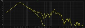
I realised too late what the measurement was of. It would be interesting to see a measurement of what comes out of the port at higher levels with the crossover in place.

I don't know about higher levels since i haven't measured it yet but i simulated port response in REW with crossover frequency at 250Hz and it looked great - even when 400Hz resonance was visible. I'll post that later when i get back home.
 
Last edited:

tuga

Major Contributor
Joined
Feb 5, 2020
Messages
3,984
Likes
4,285
Location
Oxford, England
On axis some diffraction products are visible. My guess is that it origins from tangerine phase plug. It is very mild though and tangerine waveguide enables it to have such a great off axis response above 10kHz.
I think that Kef defines 10° off-axis as optimal, either in an interview or in print (can’t recall).
 
  • Like
Reactions: Zvu

tuga

Major Contributor
Joined
Feb 5, 2020
Messages
3,984
Likes
4,285
Location
Oxford, England
@Zvu wouldn’t it make sense to add “build” or “DIY build” to the topic title?
As it stands I almost missed it and it would have been a great loss as it’s very interesting.
 
OP
Zvu

Zvu

Addicted to Fun and Learning
Joined
May 1, 2020
Messages
831
Likes
1,421
Location
Serbia
Of course it makes sense. When starting the thread i never intended to make it diy build but more of a review of Kef DC. It diverged very early and i never thought about contacting the admins/mods to move thread in DIY sub-forum.

Lemme see what i can do about it now :)
 
Last edited:
OP
Zvu

Zvu

Addicted to Fun and Learning
Joined
May 1, 2020
Messages
831
Likes
1,421
Location
Serbia
.............It would be interesting to see a measurement of what comes out of the port at higher levels with the crossover in place.

As promised, port response with filter in place, LR4 at 250Hz simulated with REW.

Порт са филтером.jpg

Lower line with filter ON.
 

fluid

Addicted to Fun and Learning
Joined
Apr 19, 2021
Messages
694
Likes
1,198
As promised, port response with filter in place, LR4 at 250Hz simulated with REW.
When you get to measure it that will be a good graph to compare against :)
 
OP
Zvu

Zvu

Addicted to Fun and Learning
Joined
May 1, 2020
Messages
831
Likes
1,421
Location
Serbia
Agreed. That could happen soon. Though REW filter simulator works quite well so i don't expect much discrepancies when measuring.
 

TLEDDY

Addicted to Fun and Learning
Forum Donor
Joined
Aug 4, 2019
Messages
641
Likes
870
Location
Central Florida
As usual, I am in awe of the talent on this Forum!
 

Nusse

Member
Forum Donor
Joined
Jan 1, 2019
Messages
20
Likes
58
Location
Sweden
Maybe time to start my own thread...

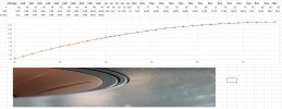
Finally my brother did a first milling test out of a solid 12 mm thick aluminium plate (~220x 250 mm).

The lower thick line is the original flare.
org_vs_alu2.JPG

As you can see the plate was not perfectly flat, but this was just a first test
20211227_155405.jpg
20211227_160211.jpg
20211227_155435.jpg
 

D!sco

Senior Member
Joined
Jun 16, 2021
Messages
498
Likes
399
Very cool build. Love the quality of your 3D printed components. Have you thought about anodizing the aluminum waveguide?
 
  • Like
Reactions: Zvu

Alex1022000

New Member
Joined
Mar 30, 2022
Messages
3
Likes
13
It still looks macho enough with flares.

View attachment 132573View attachment 132574

There is still one "little" problem - how to mount the flare to the cabinet. It has to be removable, to not suffer from flare popping out and preferably without any visible screws.

I've been thinking to attach bolt heads on the back of the flare (by melting them into the flare or drill shallow holes and epoxying), then drill through the front baffle and use nuts from behind to attach them. As if that doesn't sound complicated enough, it would require that cabinet rear baffle and rear baffle from midrange chamber remain removable. I did plan to leave rear speaker baffle removable, but didn't plan that for midrange chamber, though i can do it.

If anyone has any fresh idea, do share.
I like the Flare very much, do i unterstand it correctly that ist consist out of 2 3d printed peaces?
is it possible that u might share the updated 3d files?

i ordered the original flares for a project of mine but i am waiting since december so maybe i can try yours
 

Nusse

Member
Forum Donor
Joined
Jan 1, 2019
Messages
20
Likes
58
Location
Sweden
Very cool build. Love the quality of your 3D printed components. Have you thought about anodizing the aluminum waveguide?
Yes, from the very beginning. Have the equipment. Just need to do it.
 
OP
Zvu

Zvu

Addicted to Fun and Learning
Joined
May 1, 2020
Messages
831
Likes
1,421
Location
Serbia
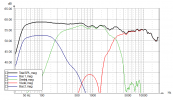
Still waiting for things to loosen up a bit regarding covid to get the permission to go to the school gym and measure drivers with longer gate (at least over 10ms) for precise crossover design. In the meantime, it doesn't mean i can't play at home to get the feal of the drivers and what could work for crossover. I made files on axis and roughly 35-40 degrees off axis. That way i can track what will happen, and since i made 0-90 degrees measurements of raw drivers before, i know if it will hold over 40 degrees..

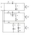
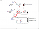
I wanted to see how would Kef's topology from their whitepaper work. This is schematic.

skretnica.png

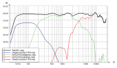
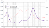
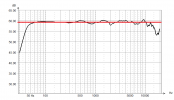
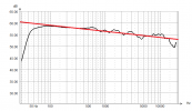
For woofers, if we disregard L5, it's how i usually do woofer crossover in a threeways with relatively low crossover points (under 800Hz). I used L5 on this test run just to see what will it do. It makes a notch at about 1000Hz (visible from Erin's nearfield measurements). Usually i add a small capacitor over L4 to make a bottomless notch - i aim at the cone resonance. You must keep track of the impedance to see what happens and make it a tank filter if needed. Added small cap over L2 on the midrange aswell and a 3.3uF capacitor shunt to midrange. Didn't do too much but i thought it was worth it since it cleared things over 8kHz. I haven't messed with tweeter crossover since it is about right. I can make it different but not wildly better in any way. I thought that C2 is some small value cap but when i begun simulating it looked like larger value makes much more sense since it is used to shape the response of the tweeter. We still have small resonance in the tweeter around 2kHz which i observed in LS50 and Q100 raw measurements. So, here's what i got with a few hours of playing:

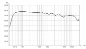
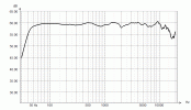
On axis:
Одзив учестаности на оси.png 1.png

Off axis:
Одзив учестаности ван осе.png 2.png

Impedance:
Импеданса.png

And dancing curve :)
Анимација.gif

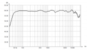
As far as linearity goes, it looks like this:
11.png 22.png

Not too shabby :) Now, i'm not saying that i've hit the right values, but that looks darn impressive to me given that i use complettely different woofers and somewhat different front baffle also. Here is the crossover. I left visible only values of components i added out of respect for Kef engineers. Oh, and these drivers are made for shaaaaallow slopes. When ever i tried to make slopes steeper, things tend to go to hell. With DSP active it wouldn't be a problem but with passive ? Jesus, Mary and Joseph. Didn't enjoy that attempt at all.

Скретница.png

Anyhow, fun stuff :)
 
Last edited:

babaudio

New Member
Joined
Dec 12, 2022
Messages
3
Likes
0
Here's .STEP file for 3D printing of shadow flare - courtesy of @Nusse
The diameter of the SP1753CA flange is 108mm, diameter
RING_V4 is 105.2mm. What speaker was RING_V4 designed for?
 

Attachments

  • RING_V4.pdf
    277.2 KB · Views: 62

babaudio

New Member
Joined
Dec 12, 2022
Messages
3
Likes
0
I wasn't aware of this thread until now :)
I did measure the midrange cone and the surround with an optical measurement equipment and had my brother print a flare. I think the flare is quite similar to the original that I have in my R3.

Will follow this thread closely as I also have an extra pair of the new R Uni-Q drivers.

View attachment 130075
The diameter of the SP1753CA suround is 108mm, the flare starts at a diameter of 55 x 2 = 110mm. This corresponds to the 1mm gap in the picture. I.e. I would believe this profile to be correct.
 

Attachments

  • hmprf.JPG
    hmprf.JPG
    139.3 KB · Views: 70

babaudio

New Member
Joined
Dec 12, 2022
Messages
3
Likes
0
Can someone share the current verified (measured) flare shape for SP1753CA, step model or drawing ?
 
OP
Zvu

Zvu

Addicted to Fun and Learning
Joined
May 1, 2020
Messages
831
Likes
1,421
Location
Serbia
The diameter of the SP1753CA flange is 108mm, diameter
RING_V4 is 105.2mm. What speaker was RING_V4 designed for?

That's for R300 coax - uploaded instead of R3 by mistake.
 
Top Bottom