-
WANTED: Happy members who like to discuss audio and other topics related to our interest. Desire to learn and share knowledge of science required. There are many reviews of audio hardware and expert members to help answer your questions. Click here to have your audio equipment measured for free!
You are using an out of date browser. It may not display this or other websites correctly.
You should upgrade or use an alternative browser.
You should upgrade or use an alternative browser.
Kef R series dual concentric
- Thread starter Zvu
- Start date
BrokenEnglishGuy
Major Contributor
- Joined
- Jul 19, 2020
- Messages
- 1,936
- Likes
- 1,158
A carbon fiber shadow flare... very impressive sirReally nice!
I've been lazy, but had my brother milling an aluminium mold to try out the Prepreg carbon fibre stuff I bought almost a year ago...
First attempt.
Looking at the former midrange/tweeter parameters https://www.erinsaudiocorner.com/driveunits/kef-r300-drive-unit/ Displacements limits was 1,5 mm. Assuming Pmax 100 W The SW I use Max Output Level (MOL) starts falling from ~350 Hz and down. Increasing displacement to 2,5 mm MOL starts falling from ~300 Hz. Do you think /know if it is possible to have a x-over below 350 Hz without limiting MOL?Since i intend to put crossover point between 200-400Hz
Last edited:
- Thread Starter
- #45
@Nusse Lets do a sim, it is quite simple. I used TS parameters for R300 coax provided from Erin's audio corner website. I chose 2 liter closed cabinet since that is most similar to factory R series midrange enclosure.
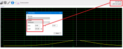
If we apply just 12dB/o highpass filter at 250Hz to midrange, we get loudness of 107dB/1m/100W - and that is still linear excursion.
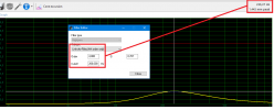
By applying 4th order we can push the crossover point down to 200Hz and still be in the linear domain.
Now, this is simulation for "old" R series midrange. Limiting factor was suspension that along with magnet system has undergone changes that boosted distortion performance.
I woudn't be too worried about it. But if you want, you can post TS parameters for low frequency transducers you intend to use and i'll do a sim or two to make sure everything is ok.
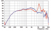
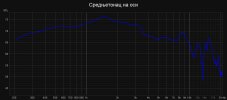
Oh, and i must give credit to KEF for consistency. Here is Kef measurement of midrange on axis in blue and mine measurement next to it.
If we apply just 12dB/o highpass filter at 250Hz to midrange, we get loudness of 107dB/1m/100W - and that is still linear excursion.

By applying 4th order we can push the crossover point down to 200Hz and still be in the linear domain.

Now, this is simulation for "old" R series midrange. Limiting factor was suspension that along with magnet system has undergone changes that boosted distortion performance.

I woudn't be too worried about it. But if you want, you can post TS parameters for low frequency transducers you intend to use and i'll do a sim or two to make sure everything is ok.
Oh, and i must give credit to KEF for consistency. Here is Kef measurement of midrange on axis in blue and mine measurement next to it.


Last edited:
BrokenEnglishGuy
Major Contributor
- Joined
- Jul 19, 2020
- Messages
- 1,936
- Likes
- 1,158
Can these Shadow flare improve the stock?, the stock shadow flare have a trade because if you use the flare in you got a 1dB of dip in 700hz, but with the flare out the dip its gone, its possible do make a new one for get the best of the flare out and in ?, the response gonna smoth a litlle bit and also its better looking if looks like the referenceIt started like this:
View attachment 132558View attachment 132559
2mm steel, laser cut ring. Diameter is 150mm, hole diameter is 115mm. Suspension rubber is about 2.3mm thick so it makes flare near suspension sit on the hard rubber part glued to the midrange frame. Since it is not stainless but regular steel, it needed some coating to prevent rust and since i'm confident in my sexuality
View attachment 132560View attachment 132562
Driver opening in speaker baffle will be as large as the diameter of midrange is. Ring is the medium between the front baffle and the driver chassis. You'll notice that the screw holes aren't lined up. That is not by mistake. If anyone noticed on previous pictures, screw holes on chassis do not line up with the spokes on the basket. Trying to get minimum diffraction, i intend to chamfer the back of the midrange baffle between spokes to allow midrange to breathe, but i will keep extra thickness where mounting screws go in to the MDF. Similar to THIS.
View attachment 132563
If you are asking yourself am i exaggerating i'd usually say -probably-. But i noticed that the aluminium frame in midrange has its own chamfer and if at KEF they cared enough to make it, it is probably wise to invest some thinking in to minimum shading of midrange cone. I intend to make the baffle chamfer continue from chamfer molded in frame. I don't know how visible frame chamfer is but here it is:
View attachment 132564
Screw heads would get in the way but Magnus (aka Nusse) predicted it in printed version so they align perfectly with small holes on the back of the flare.
View attachment 132565
Thanks to Erin for this graph

Please do@Nusse I'll send you a drawing of shadow flare how i think would work best with neodimium magnets. If your brother can make a file for 3D printer based on that, we can upload it here for download by anyone interested. Ok
- Thread Starter
- #51
Can these Shadow flare improve the stock?, the stock shadow flare have a trade because if you use the flare in you got a 1dB of dip in 700hz, but with the flare out the dip its gone, its possible do make a new one for get the best of the flare out and in ?, the response gonna smoth a litlle bit and also its better looking if looks like the reference
Thanks to Erin for this graph

As i've understood Erin's measurements, best thing you can do with stock flares is to push them in as much as you can until the suspension is flat with flare. I'm not sure it is worth the effort to rip the flares and modify factory cabinets. If you want it to look as in Reference, take the flares out, lightly sand them with 800-1000 grit sandpaper and spray them with some primer for plastic and paint you like for finish.
.........
Will you measure distorsion at low freq and high SPL?
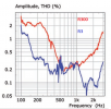
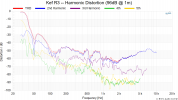
I've been thinking about this a little bit... Erin measured distortion for R3 that utilizes this coax at Erin's audio corner website at 86dB/1m and 96dB/1m.
Since it is crossed at 400Hz and 2900Hz with pretty shallow slopes, distortion graph is quite valid to observe. At 96dB/1m up to 1kHz we have 0.3% HD2 while HD3 is at staggeringly low 0.1%. Over 1kHz though HD2 falls to 0.1% while HD3 goes down to -70dB which is equal to 0.03% distortion.
And as if that isn't enough, Soundstage Network magazine did distortion measurements at 95dB but at 2m and above 200Hz there is no sign of distortion stress.
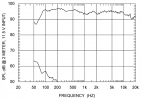
I'm wondering is there really any actual need for additional distortion measurements since i'll hardly match Klippel and Bruel & Kjaer equipment regarding distortion accuracy. If we want to compare it, Kef R coax has distortion at 96dB from 300-3000Hz almost as low as any of Purifi 6,5's
Last edited:
BrokenEnglishGuy
Major Contributor
- Joined
- Jul 19, 2020
- Messages
- 1,936
- Likes
- 1,158
The best result its the shadow flare pushing in with your fingers, so the shadow flare its flat with the suspension as you saidAs i've understood Erin's measurements, best thing you can do with stock flares is to push them in as much as you can until the suspension is flat with flare. I'm not sure it is worth the effort to rip the flares and modify factory cabinets. If you want it to look as in Reference, take the flares out, lightly sand them with 800-1000 grit sandpaper and spray them with some primer for plastic and paint you like for finish.
I've been thinking about this a little bit... Erin measured distortion for R3 that utilizes this coax at Erin's audio corner website at 86dB/1m and 96dB/1m.
Since it is crossed at 400Hz and 2900Hz with pretty shallow slopes, distortion graph is quite valid to observe. At 96dB/1m up to 1kHz we have 0.3% HD2 while HD3 is at staggeringly low 0.1%. Over 1kHz though HD2 falls to 0.1% while HD3 goes down to -70dB which is equal to 0.03% distortion.
View attachment 162763 View attachment 162765
And as if that isn't enough, Soundstage Network magazine did distortion measurements at 95dB but at 2m and above 200Hz there is no sign of distortion stress.
View attachment 162764
I'm wondering is there really any actual need for additional distortion measurements since i'll hardly match Klippel and Bruel & Kjaer equipment regarding distortion accuracy. If we want to compare it, Kef R coax has distortion at 96dB from 300-3000Hz almost as low as any of Purifi 6,5's
But maybe if the shadow flare its flat to the cabinet and also the uniq suspension, the 750hz dip may dissapiar
PD are you using the uniq from r300 or r3?
Last edited:
- Thread Starter
- #53
First thing i'd do (if i was in posession of kef R loudspeaker) is try to make the transition from flare to baffle as mild as i can, with measurements before and after of course. That way i would know for sure if that's the problem.
If it is responsible for that dip, making the flare line up with suspension and baffle might work.
On the other hand, it is dip of just 1dB or so. I probably wouldn't waste my time with correcting that before i check audibility of it by simply adding +1dB eq at that spot.
If it is responsible for that dip, making the flare line up with suspension and baffle might work.
On the other hand, it is dip of just 1dB or so. I probably wouldn't waste my time with correcting that before i check audibility of it by simply adding +1dB eq at that spot.
BrokenEnglishGuy
Major Contributor
- Joined
- Jul 19, 2020
- Messages
- 1,936
- Likes
- 1,158
To be honest with my R7 if I add 1dB in 700hz make no much difference.. The speaker already sound nice...First thing i'd do (if i was in posession of kef R loudspeaker) is try to make the transition from flare to baffle as mild as i can, with measurements before and after of course. That way i would know for sure if that's the problem.
If it is responsible for that dip, making the flare line up with suspension and baffle might work.
On the other hand, it is dip of just 1dB or so. I probably wouldn't waste my time with correcting that before i check audibility of it by simply adding +1dB eq at that spot.
But maybe its a ooportunity for making a better in looking and performance shadow flare
- Thread Starter
- #55
Midrange and tweeter measure as predicted. Now i have to focus on bass response and performance. Further investigation is all about port problems and damping material distribution. We've seen that ports and their nonlinearities present problems quite often - even in very expensive loudspeakers. Let's tackle this problem.
I've chosen to use two smaller port tubes instead of one large. It is easier to find place on the back panel since struts and midrange chamber don't leave much room for it. Position of ports was more or less fixed when i decided to put enough struts so that there is no unsupported length span on any baffle larger than 10cm. I've kinda succeded with upper and lower baffle being slightly off (because of woofers position).
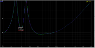
Volume behind midrange chamber is lightly stuffed (changes in stuffing density brought no progress visible on either impedance or frequency amplitude measurements).First impedance sweep looked like this:
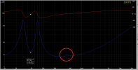
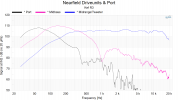
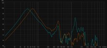
Nearfield frequency response of port and woofer are given:
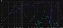
Resonance at 1200Hz is what i actually expected since my sim shows it. The one at 400Hz was somewhat of a mistery. There is a way to determine where it origins. Pulling the port out of the cabinet and remeasuring the frequency response of port opening shows resonance at the same spot. Resonance at 1200Hz is missing (shorter tube has much higher resonance - actually wall thickness acting as a port) and tuning shifted to upper frequency but the resonance at 400Hz is still there.
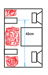
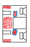
Redistributing damping material shown on the pic seemed like a logical thing to do. It was leaking standing wave through the port which was severe enough to influence the woofer response. Red is before damping material redistribution, yellow is after. Sorry for the paint quick sketches but you get the idea. Red is poly wadding and blue is modified position of it - same amount of stuffing in both cases.
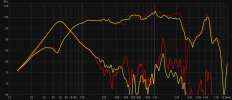
Midrange response is somewhat more linear in the region influenced by port leakage. Port performance compared here.
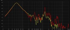
I'm guessing that there will be no nasty surprises on finished loudspeaker regarding port noise since 400Hz leakage is solved and 1200Hz is irrelevant because the woofers will cross to the midrange at 200-250Hz so port resonance won't be excitated.
I've chosen to use two smaller port tubes instead of one large. It is easier to find place on the back panel since struts and midrange chamber don't leave much room for it. Position of ports was more or less fixed when i decided to put enough struts so that there is no unsupported length span on any baffle larger than 10cm. I've kinda succeded with upper and lower baffle being slightly off (because of woofers position).
Volume behind midrange chamber is lightly stuffed (changes in stuffing density brought no progress visible on either impedance or frequency amplitude measurements).First impedance sweep looked like this:


Nearfield frequency response of port and woofer are given:

Resonance at 1200Hz is what i actually expected since my sim shows it. The one at 400Hz was somewhat of a mistery. There is a way to determine where it origins. Pulling the port out of the cabinet and remeasuring the frequency response of port opening shows resonance at the same spot. Resonance at 1200Hz is missing (shorter tube has much higher resonance - actually wall thickness acting as a port) and tuning shifted to upper frequency but the resonance at 400Hz is still there.

Redistributing damping material shown on the pic seemed like a logical thing to do. It was leaking standing wave through the port which was severe enough to influence the woofer response. Red is before damping material redistribution, yellow is after. Sorry for the paint quick sketches but you get the idea. Red is poly wadding and blue is modified position of it - same amount of stuffing in both cases.


Midrange response is somewhat more linear in the region influenced by port leakage. Port performance compared here.

I'm guessing that there will be no nasty surprises on finished loudspeaker regarding port noise since 400Hz leakage is solved and 1200Hz is irrelevant because the woofers will cross to the midrange at 200-250Hz so port resonance won't be excitated.
Last edited:
If you have some try foam and felt, in my own experiments poly wadding had no significant measurable effect on cabinet resonances.Redistributing damping material shown on the pic seemed like a logical thing to do. It was leaking standing wave through the port which was severe enough to influence the woofer response. Red is before damping material redistribution, yellow is after. Sorry for the paint quick sketches but you get the idea. Red is poly wadding and blue is modified - same amount of stuffing in both cases.
https://www.diyaudio.com/forums/full-range/303417-range-tc9-line-array-cnc-cabinet-post5053920.html
Last edited:
- Thread Starter
- #58
Poly wadding isn't a great material in its original form but densely rolled and packed in strategic places does wonders - as can be seen from my measurements. I see no port leakage worth mentioning.
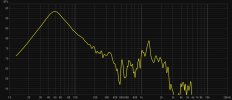
I'm not a fan of overstuffed cabinet volume. While impedance does measure slightly better than lightly stuffed, it doesn't sound better to me. I use foam in some occasions but felt i try to avoid since it is a black hole for sound.

I'm not a fan of overstuffed cabinet volume. While impedance does measure slightly better than lightly stuffed, it doesn't sound better to me. I use foam in some occasions but felt i try to avoid since it is a black hole for sound.
Last edited:
Then I must have misunderstood your description of what you did.Poly wadding isn't a great material in its original form but densely rolled and packed in strategic places does wonders - as can be seen from my measurements.
Which is the reason why I like to use it, each to their ownI use foam in some occasions but felt i try to avoid since it is a black hole for sound.
I realised too late what the measurement was of. It would be interesting to see a measurement of what comes out of the port at higher levels with the crossover in place.I see no port leakage worth mentioning.

