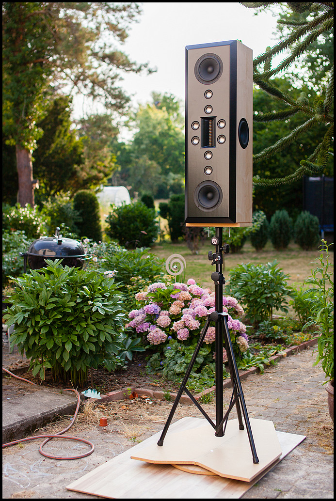
If this is true, one could instead of a uniQ driver use a 4 inch driver and a tweeter with minimal faceplate and mount them very close and do the crossover at 2 kHz . In this way , you should avoid the bassdriver modulating the tweeter, as Erin has shown before.
But the fact is - I feel thats something more with the uniQ drivers, maybe its the low distortion tweeter they use ?
That is doppler distortion.
So technically one could also prevent the woofer from have to much excursion
")
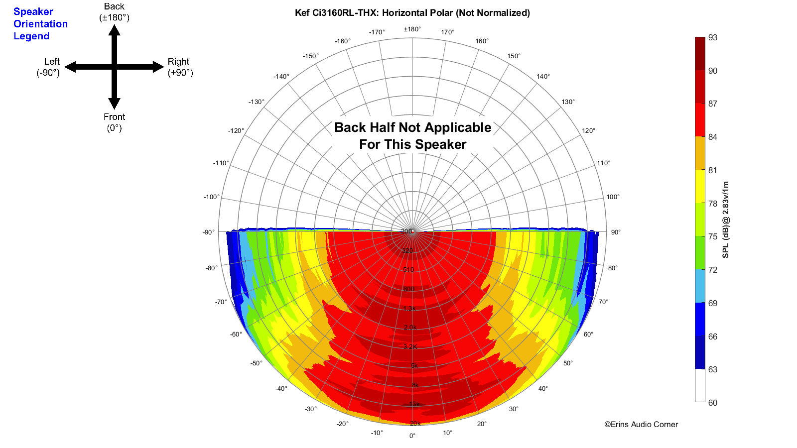
One of the compromises of coaxial speakers, is the shape of the cone.
For rigidity purposes, as well having a nice off-axis response the woofer needs a different shape than what is suitable for a waveguide for the tweeter.
For the tweeter a CD-waveguide or a Oblate Spheroid Waveguide is needed to have proper constant directivity.
Which doesn't really suit very well with what is needed for the woofer in sense of unwanted cone resonances.
As for the wavelength difference, this all depends what exactly you're looking for.
The frequency of this difference can be calculated with;
f = v / (2·D·sin(a) )
Where;
f = frequency
v = speed of sound
D = distance between sound sources in meters (center-to-center distance)
a = angle in degrees.
So for an angle of 90 degrees (= max difference in wavelength), we can skip the
sin(a) term, since it will be 1.
A center-to-center distance of 15cm gives us around 1146Hz.
Although in practice the frequency already starts dipping before.
So it's not easy to get this super well, especially when one wants to use a nice waveguide for the tweeter.
Which is a MUST for a good directivity.
I am not concerned about tweeter distortion, these days this distortion is low enough from any decent manufacturer.

www.diyaudio.com
 Also what do you mean with test sample and "tuned"?