Way back in 1970 Wireless world published another form of tone control to complement the standard Baxandall bass and treble control:
https://keith-snook.info/wireless-world-articles/Wireless-World-1970/Tone-balance Control DCD.pdf


A single potentiometer control simultaneously provides both bass-boost and treble-cut or, alternately, bass-cut and treble-boost, depending on which direction from center (flat response) it is turned. Hence the name "tone-balance control" - the balance being between bass frequencies and treble frequencies.
I hate Baxandall bass and treble controls as they are almost universally designed with a mutual bass/treble contour crossover in the vicinity of 1kHz. A bass control in particular that has a significant influence to near 1kHz is terrible for compensating speakers with limited bass response because it is crossed far too high. What you get with such a control is an audibly unpleasant boosting and muddying of the lower mid-range.
The Baxandall tone control is much better designed so that the bass and treble controls leave the region of 500Hz to 2kHz alone.
This is where I see the tone-balance control as a addition to the Baxandall bass and treble control to have merit. The Baxandall controls can be used for correction while the tone-balance knob can then take on the role of the altering the balance between bass and treble frequencies to your subjective preference.
Quad was one of few manufacturers that adopted the tone-balance control, calling it a "tilt" tone control. The problem with the basic circuit, however, is that its tilt response is sharpest in the mid-range:

So it is more like a control that gives an alternate boost and cut to bass and treble frequencies respectively (or vice-versa) rather than something that gently and progressively "tilts" the frequency response to your subjective preference from one end of the spectrum to the other. As a matter of fact, at any setting the frequency response is very close to that of the Baxandall tone control (as it is typically poorly implemented) with the treble control set to an equal and opposite level of boost to the bass control.
I've been looking at Quad schematics. In the Model 34 control unit the tilt balance control is implemented in a single stage along with a bass boost/cut control. There is no independent treble control:

It appears that the Quad designers had similar concerns to me, as they have used parallel RC networks with stepped frequency crossovers in this variant of the tilt-tone control circuit in an attempt to broaden and flatten out the tilted response about the crossover frequency.
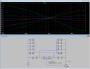
The improvement, however, is rather modest. I've gone back the original circuit by Ambler and have started to experiment with the same approach, but expanded with a greater number of stepped RC networks. The approach looks promising so far.
The aim is to get a frequency response curve that is a good approximation to a straight, tilted line between 20 Hz and 20 kHz, which demands a see-saw pivot at about 1 kHz for an equal level of influence at either end of the spectrum.

https://keith-snook.info/wireless-world-articles/Wireless-World-1970/Tone-balance Control DCD.pdf
A single potentiometer control simultaneously provides both bass-boost and treble-cut or, alternately, bass-cut and treble-boost, depending on which direction from center (flat response) it is turned. Hence the name "tone-balance control" - the balance being between bass frequencies and treble frequencies.
I hate Baxandall bass and treble controls as they are almost universally designed with a mutual bass/treble contour crossover in the vicinity of 1kHz. A bass control in particular that has a significant influence to near 1kHz is terrible for compensating speakers with limited bass response because it is crossed far too high. What you get with such a control is an audibly unpleasant boosting and muddying of the lower mid-range.
The Baxandall tone control is much better designed so that the bass and treble controls leave the region of 500Hz to 2kHz alone.
This is where I see the tone-balance control as a addition to the Baxandall bass and treble control to have merit. The Baxandall controls can be used for correction while the tone-balance knob can then take on the role of the altering the balance between bass and treble frequencies to your subjective preference.
Quad was one of few manufacturers that adopted the tone-balance control, calling it a "tilt" tone control. The problem with the basic circuit, however, is that its tilt response is sharpest in the mid-range:
So it is more like a control that gives an alternate boost and cut to bass and treble frequencies respectively (or vice-versa) rather than something that gently and progressively "tilts" the frequency response to your subjective preference from one end of the spectrum to the other. As a matter of fact, at any setting the frequency response is very close to that of the Baxandall tone control (as it is typically poorly implemented) with the treble control set to an equal and opposite level of boost to the bass control.
I've been looking at Quad schematics. In the Model 34 control unit the tilt balance control is implemented in a single stage along with a bass boost/cut control. There is no independent treble control:
It appears that the Quad designers had similar concerns to me, as they have used parallel RC networks with stepped frequency crossovers in this variant of the tilt-tone control circuit in an attempt to broaden and flatten out the tilted response about the crossover frequency.
The improvement, however, is rather modest. I've gone back the original circuit by Ambler and have started to experiment with the same approach, but expanded with a greater number of stepped RC networks. The approach looks promising so far.
The aim is to get a frequency response curve that is a good approximation to a straight, tilted line between 20 Hz and 20 kHz, which demands a see-saw pivot at about 1 kHz for an equal level of influence at either end of the spectrum.
Attachments
Last edited:
