Also some other source of this issue. Board layout. Power supply ground should be as close to the output as possible. The input ground should be taken directly from the output ground instead of the power supply ground.

-
WANTED: Happy members who like to discuss audio and other topics related to our interest. Desire to learn and share knowledge of science required. There are many reviews of audio hardware and expert members to help answer your questions. Click here to have your audio equipment measured for free!
You are using an out of date browser. It may not display this or other websites correctly.
You should upgrade or use an alternative browser.
You should upgrade or use an alternative browser.
How to reduce 120Hz frequency at amp output?
- Thread starter pkane
- Start date
restorer-john
Grand Contributor
DUT amplifier input to be shorted.
This is important. Use a metal RCA plug with a solder link from hot to outer.
restorer-john
Grand Contributor
It's probably the interference from the magnetic field from the transformer.
Sure 60Hz is there, but it's the 120Hz that is dominating, and that's not radiated from the TXF. It's post bridge rectifier.
It's probably the interference from the magnetic field from the transformer. If you are able to place the transformer further from the circuit, there is high chance that you will see it being reduced.
Btw 65uV hum is huge. 2uV or lower is good. And i only see 200nV or lower as high performance.
Do you also speak about 400W class AB amplifier as I do? (200nV you are saying, any proof, measurements?)
It's not a matter of how many watts. I'm currently designing an power amp with lower wattage that will out perform ahb2 in distortion and noise, which can scale up to high power as well. If the input stage is regulated there is no difference. And I will show some measurements a few minutes later.Do you also speak about 400W class AB amplifier as I do? (200nV you are saying, any proof, measurements?)
Update: It's 1uV not very low but I consider this good. Rca input, which is important in this measurement.
Last edited:
A bit higher with 4ohm load. Rising ps noise with load can be cured with higher capacitor. I'm only using 3300uF here.
@84FXJV$P`1K`ET~7B9G.png")
OP
- Thread Starter
- #27
First, please always specify the level to which dB plot is related. dB is a relative number and depends what is the 0dB voltage level. 1V? 7V? Anything else?
Then I would start with (4), possible mains frequency throughput into measuring system. To check, please try a setup as below.
1) disconnect any ground loop.
2) turn the amp on. Connect measuring cable to amp speaker binding post as shown, both live and gnd of the measuring cable to the amp binding post that is at signal ground. Measure the spectrum with the soundcard and this will tell the residual measurement error. DUT amplifier input to be shorted.
View attachment 44677
Even some linear amps may have very low hum voltage, like this Parasound
View attachment 44678
The output voltage for that plot was 16v.
This is not a 60Hz mains frequency harmonic since 120Hz signal is significantly higher than 60Hz. The rest of the system was not connected to the mains, so it’s unlikely coming from that (PC and interface powered by battery).
I’ll try the shorted input test and report back.
It's highly possible just due to the drained caps. And transformer interference can also generate higher 120hz than 60hz. As long as it's harmonics of 60hz, it is all possible. You may try just measure without any load. And you may also try to have a connection between the ground of measurement equipment or a external earth ground and the amplifier input ground/or output ground.The output voltage for that plot was 16v.
This is not a 60Hz mains frequency harmonic since 120Hz signal is significantly higher than 60Hz. The rest of the system was not connected to the mains, so it’s unlikely coming from that (PC and interface powered by battery).
I’ll try the shorted input test and report back.
A bit higher with 4ohm load. Rising ps noise with load can be cured with higher capacitor. I'm only using 3300uF here.OK
It is usually a question of transformer size and filter capacitors returns. I doubt that increasing capacitance would help, because charging current impulses have much higher amplitude then and this is what affects magnetic coupling into amp PCB.
restorer-john
Grand Contributor
It's highly possible just due to the drained caps.
No, you're dreaming.
So are you certain what the cause is? if not then there is nothing wrong with what i was saying.No, you're dreaming.
Well that depends. I have actually no idea what exactly the cause of mains hum in other amplifiers. It should be a mixture of multiple sources. With smps it can be even worse. With my current test amp, I can just try a different value and see what happens. It's at this low level the source that weren't important can be significant.It is usually a question of transformer size and filter capacitors returns. I doubt that increasing capacitance would help, because charging current impulses have much higher amplitude then and this is what affects magnetic coupling into amp PCB.
One little thing I learn in ground layout is that input/signal(Rg ground) ground should directly connect to the output ground without connect to any other ground. And the power supply capacitor/regulator (if there is) should be as close as possible to the output terminal. This way you will reduce lots and lots of distortion and mains hum. If you already know this just omit what I just said, if not you may try that.
OP
- Thread Starter
- #33
Well that depends. I have actually no idea what exactly the cause of mains hum in other amplifiers. It should be a mixture of multiple sources. With smps it can be even worse. With my current test amp, I can just try a different value and see what happens. It's at this low level the source that weren't important can be significant.
One little thing I learn in ground layout is that input/signal(Rg ground) ground should directly connect to the output ground without connect to any other ground. And the power supply capacitor/regulator (if there is) should be as close as possible to the output terminal. This way you will reduce lots and lots of distortion and mains hum. If you already know this just omit what I just said, if not you may try that.
Input level didn’t have any effect on the 120Hz component. Here’s an extremely low level 1kHz signal playing through the amp:
Several sources are possible:
1. Caps aging, sure. But at low powers, the PSR of the circuit will likely dominate. One way to be sure is to take a spectrum of the power rails.
2. Transformer radiation. If you have a full wave rectifier, the radiation pickup from the secondary will be at 120Hz.
3. Wiring radiation. High current pulses from the rectification and filtering can be emitted and coupled into the signal circuitry.
4. Power supply and audio grounding layout. This can be a bit tricky in the PCB design, where IR drops of ripple currents get injected into the signal circuitry.
Then it's unlikely to be the caps. If you are comfortable with electricity, measure the output voltage of the transformer, replace with a DC source and connect to where the dc should go(after rectification), or an external transformer to avoid interference. You can also try directly connect an earth connection to input ground or output ground. Does it have more or less mains hum? Is there a device that doesn't have mains hum to compare with? There are certainly a lot of thing that you can do but it can be difficult if you don't have those. It can also be the amplifier just isn't that good the input stage fluctuates with supply.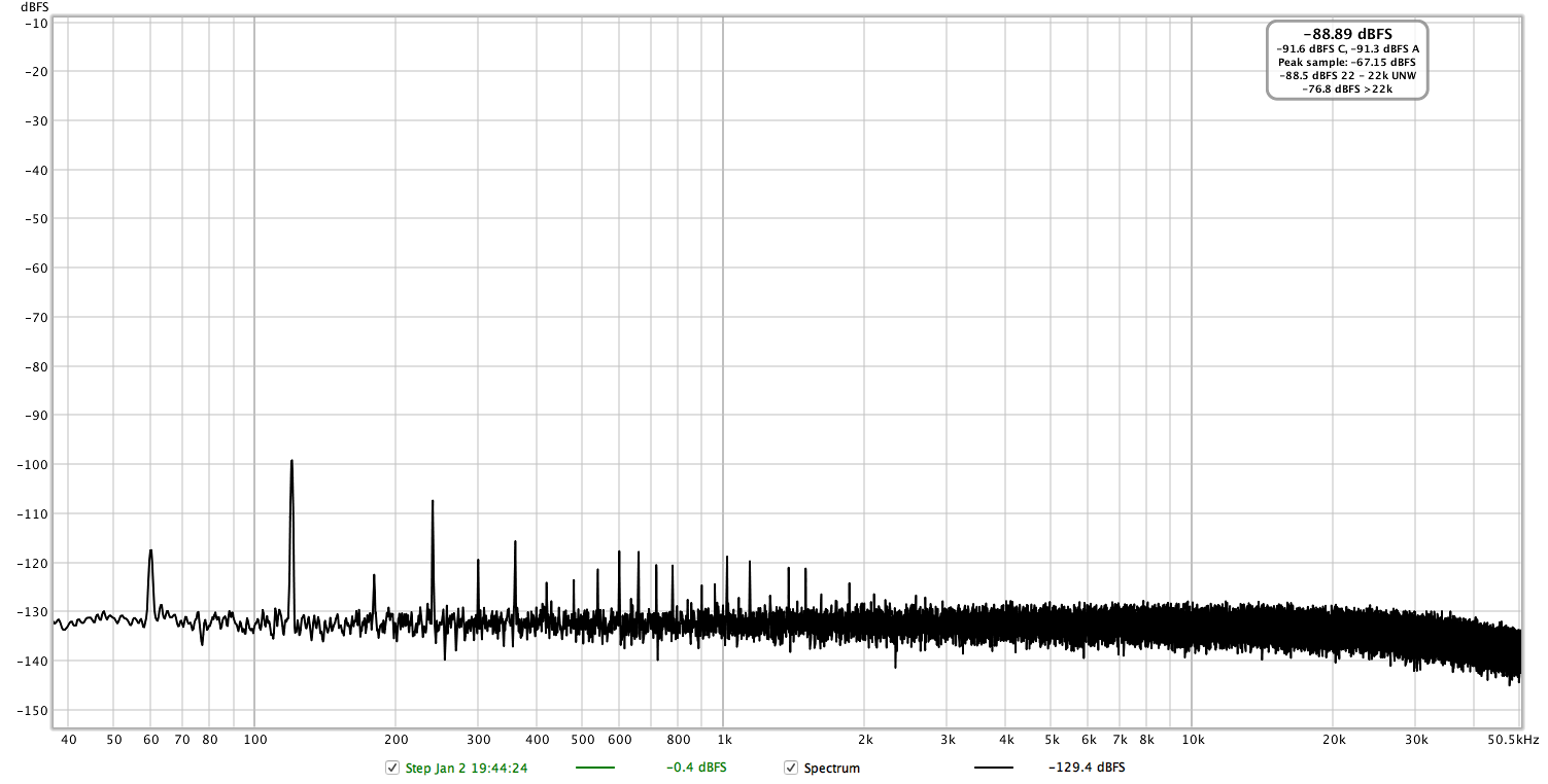
Input level didn’t have any effect on the 120Hz component. Here’s an extremely low level 1kHz signal playing through the amp:
Well said!Several sources are possible:
1. Caps aging, sure. But at low powers, the PSR of the circuit will likely dominate. One way to be sure is to take a spectrum of the power rails.
2. Transformer radiation. If you have a full wave rectifier, the radiation pickup from the secondary will be at 120Hz.
3. Wiring radiation. High current pulses from the rectification and filtering can be emitted and coupled into the signal circuitry.
4. Power supply and audio grounding layout. This can be a bit tricky in the PCB design, where IR drops of ripple currents get injected into the signal circuitry.
Ok, maybe I feel dumb. I’m still using standard generic twin RCA cables on some of my gear. (XLR balanced on my DAC to Amp at least). Should I unzip them for a few dB improvement in crosstalk? Or were you joking?I agree. It certainly is strange, but a lot of people back then used twin RCA leads and if you were like me, you didn't want to pull them apart.
Now, everyone pretty much uses individual RCA L/R cables and we like our inputs to be separated by a decent distance on "dual mono" gear.
")

Last edited:
KSTR
Major Contributor
Don't unzip them, this increases loop area to pick up magnetic field causing a circulating current through the shields. Voltage drop along the shield then produces a noise voltage (out-of-phase between channels).
@amirm : good signal integrity / EMC practise says "keep all your connectors and cabels together"... up to the point when measured crosstalk actually raises.
@amirm : good signal integrity / EMC practise says "keep all your connectors and cabels together"... up to the point when measured crosstalk actually raises.
I have not read through all the posts. I do want to clarify that I was suggesting a means of measuring the capacitors' values, not that they were the cause of the noise. On caps aging, the circuit should reject that to a large degree (PSRR, CMRR, etc.), so I would look for other coupling sources around or after the bridge rectifier since you see 120 Hz. Coupling paths can be tricky to ascertain since they can be induced ground/signal currents, radiated and picked up at the inputs or gain stages, injected along the feedback path, etc.
My brief skim is that John et. al. have covered the subject quite well, as usual, so have nothing to contribute.
My brief skim is that John et. al. have covered the subject quite well, as usual, so have nothing to contribute.
OP
- Thread Starter
- #40
It's highly possible just due to the drained caps. And transformer interference can also generate higher 120hz than 60hz. As long as it's harmonics of 60hz, it is all possible. You may try just measure without any load. And you may also try to have a connection between the ground of measurement equipment or a external earth ground and the amplifier input ground/or output ground.
@pma :
The shorted input appears to have no significant impact on the level of the 120Hz frequency, but it does tame the 60Hz that is much more prominent when the input is left completely open (shorted input is the red trace):
Considering that both channels have nearly exactly the same level of this 120Hz signal, I think that @restorer-john is right that this is not due to capacitor aging. Possibly a transformer induced frequency or some other design flaw that's not properly filtered out. I'll probably stop looking at this point, as I'm not going to mod this amplifier to reduce hum that's already not audible
Thank you for everyone's input, I learned a lot!
Last edited:
Similar threads
- Replies
- 676
- Views
- 72K
- Replies
- 48
- Views
- 13K
- Replies
- 12
- Views
- 996
- Poll
- Replies
- 49
- Views
- 16K