• WANTED: Happy members who like to discuss audio and other topics related to our interest. Desire to learn and share knowledge of science required. There are many reviews of audio hardware and expert members to help answer your questions. Click here to have your audio equipment measured for free!

How do I test equipment with an analog o-scope?

FriedChicken

Active Member
Joined
Mar 10, 2021
Messages
128
Likes
53
I'm simply curious. I have an analog o-scope, and a ****** function generator. I'm wondering how I can test equipment? I even have a couple power resistors, although I don't see why a lightbulb wouldn't work lol
 

Doodski

Grand Contributor
Forum Donor
Joined
Dec 9, 2019
Messages
21,634
Likes
21,911
Location
Canada
What resistance are the power resistors?
Do you have scope probes?
What are you thinking of using the light bulbs for?
 

DVDdoug

Major Contributor
Joined
May 27, 2021
Messages
3,035
Likes
4,004
It's more useful as a troubleshooting tool to see where in a circuit you are losing the signal, etc.

You can check frequency response by checking the output voltage at different frequencies (while also using the 'scope to make sure the input-voltage doesn't change). It's usually better than a multimeter because meters often have limited frequency range (they are always good for 50Hz or 60Hz power line frequency, and probably good at 1Hz).

With sine waves you can sometimes see distortion or you can see how much output-voltage you get before clipping but I don't think you can see 1% distortion.

I don't see why a lightbulb wouldn't work lol
A cold filament has lower resistance than a hot filament. At low power it will work but you need to measure the actual resistance and the "average" multimeter isn't accurate when measuring low resistance.
 
OP
F

FriedChicken

Active Member
Joined
Mar 10, 2021
Messages
128
Likes
53
What resistance are the power resistors?
Do you have scope probes?
What are you thinking of using the light bulbs for?
Why would I have a scope without probes lol
I believe they are 8Ω resistors rated for 200W.

It's more useful as a troubleshooting tool to see where in a circuit you are losing the signal, etc.

You can check frequency response by checking the output voltage at different frequencies (while also using the 'scope to make sure the input-voltage doesn't change). It's usually better than a multimeter because meters often have limited frequency range (they are always good for 50Hz or 60Hz power line frequency, and probably good at 1Hz).

With sine waves you can sometimes see distortion or you can see how much output-voltage you get before clipping but I don't think you can see 1% distortion.

A cold filament has lower resistance than a hot filament. At low power it will work but you need to measure the actual resistance and the "average" multimeter isn't accurate when measuring low resistance.

It's a Tektronix 2213. It does have a digitizing function. My guess would be I'd have to apply some tricks to see what I'm looking for.

I have a ****** function generator from china, but I also have an iPhone with an app.
 

Doodski

Grand Contributor
Forum Donor
Joined
Dec 9, 2019
Messages
21,634
Likes
21,911
Location
Canada
Why would I have a scope without probes lol
You'de be surprised...lol

I believe they are 8Ω resistors rated for 200W.
Very nice!

It's a Tektronix 2213.
Nice basic 60MHz scope. I think I used one of those when I studied electronics. It will be more than good enough for audio and video use. For CD eye patterns you won't see the jitter very well when you magnify the time base but you'll be able to calibrate the servos and fine tune the eye pattern well enough to get a good enough calibration.

My guess would be I'd have to apply some tricks to see what I'm looking for.
What are you looking for and what tricks are you contemplating?
 
OP
F

FriedChicken

Active Member
Joined
Mar 10, 2021
Messages
128
Likes
53
I'm currently chasing down a hiss and hum from my Sony STR-DB930 when using it as a dedicated amplifier.

The center channel is the worst for hum. Weirdly, when I plugged in the receiver and probed the speaker outputs, I saw a higher noise floor on the fronts than on the others.

By tricks I mean running a sweep using my iPhone as input, and then recording that to see if there's a dip or something. Right now I'm hesitant to connect the iphone to the multi-channel inputs, b/c I don't know what voltage is "good".
 

Doodski

Grand Contributor
Forum Donor
Joined
Dec 9, 2019
Messages
21,634
Likes
21,911
Location
Canada
By tricks I mean running a sweep using my iPhone as input, and then recording that to see if there's a dip or something. Right now I'm hesitant to connect the iphone to the multi-channel inputs, b/c I don't know what voltage is "good".
According to HiFiEngine.>
Input sensitivity: 2.5mV (MM), 150mV (line)

There is a service manual available there too.
The service manual states.>
Screenshot 2022-03-03 100140.png
 

Doodski

Grand Contributor
Forum Donor
Joined
Dec 9, 2019
Messages
21,634
Likes
21,911
Location
Canada
The center channel is the worst for hum.
I provided Sony warranty service for some years and can easily state that the receivers are prone to having bad grounds. I would check that right away. I mean check the grounding on all PCBs and check the ground conductors for voltage drops across them too.
 
OP
F

FriedChicken

Active Member
Joined
Mar 10, 2021
Messages
128
Likes
53
Awesome!
Please forgive me if I start to get stupid with my questions. This level of electronics is new to me. How do I know the impedance of my iPhone?
The 150mV sensitivity means a 150mV signal will "saturate" the amplifier, and/or power it fully? This seems really really really low. Gene at audioholics wants his preamps to go up to 2VRMS? To convert VRMS to PP, you multiply by the square root of 2, yes?

The 2.5mV is for the phono preamp?


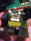
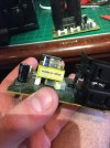
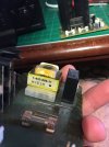
I somehow suspected a problem in the AC board, and specifically the little transformer. I heard a buzz/hum.

Poking with my continuity checker (multimeter), I found that on the input side, there was no continuity on the transformer for one of the pins (and it was being used. In the Schematic it's T902, found on page 38.

How do I very good grounding? Poke around with my multimeter, ok, but where on the PCB? And to the Chassis, correct?
 
OP
F

FriedChicken

Active Member
Joined
Mar 10, 2021
Messages
128
Likes
53
Also pictures of the suspect transformer:

What doesn't make sense to me is other than what I'm describing, the entire unit seems to work fine.
 

Attachments

  • IMG_0248.JPG
    IMG_0248.JPG
    206 KB · Views: 61
  • IMG_0249.JPG
    IMG_0249.JPG
    198.9 KB · Views: 59
  • IMG_0250.JPG
    IMG_0250.JPG
    212 KB · Views: 58

RayDunzl

Grand Contributor
Central Scrutinizer
Joined
Mar 9, 2016
Messages
13,250
Likes
17,200
Location
Riverview FL
I don't see why a lightbulb wouldn't work lol
An incandescent bulb is close to a short when cold - it's a piece of thin wire in the bulb.

But when it is lit the resistance rises...

100W bulb at 120V has a resistance of 144 ohms

1646330060154.png


---

I'm simply curious. I have an analog o-scope, and a ****** function generator. I'm wondering how I can test equipment?

My experience with analog scopes and music signals:

You can see (roughly) the voltage present during the waveform.

You can see if there's some DC offset, maybe.

You can see clipping.

That's about all, except for possible gross errors.

Lissajou patterns are kinda fun to look at, though.
 
OP
F

FriedChicken

Active Member
Joined
Mar 10, 2021
Messages
128
Likes
53
Ok, I went with my probe and probed everything I could find. I'm not sure how a grounding issue would manifest. Sometimes it took my multimeter a second or two to actually register a ground connection. This was mostly on the speaker terminals, but nothing stood out.
 
OP
F

FriedChicken

Active Member
Joined
Mar 10, 2021
Messages
128
Likes
53
An incandescent bulb is close to a short when cold - it's a piece of thin wire in the bulb.

But when it is lit the resistance rises...

100W bulb at 120V has a resistance of 144 ohms

View attachment 190181

---


My experience with analog scopes and music signals:

You can see (roughly) the voltage present during the waveform.

You can see if there's some DC offset, maybe.

You can see clipping.

That's about all, except for possible gross errors.

Lissajou patterns are kinda fun to look at, though.

Hmm. I guess it could blow an amplifier if used to test it. I have an MX-1000 I want to repair, and even my 200w resistors aren't enough potentially lol
 

Doodski

Grand Contributor
Forum Donor
Joined
Dec 9, 2019
Messages
21,634
Likes
21,911
Location
Canada
I somehow suspected a problem in the AC board, and specifically the little transformer. I heard a buzz/hum.
T902 is the standby transformer. It provides power so the CPU can power on the unit. If the unit is powering ON and OFF then that transformer is operating properly. They don't usually make a mechanical buzz/hum noise.
 

Doodski

Grand Contributor
Forum Donor
Joined
Dec 9, 2019
Messages
21,634
Likes
21,911
Location
Canada
Also pictures of the suspect transformer:

What doesn't make sense to me is other than what I'm describing, the entire unit seems to work fine.
Because you are new to component level troubleshooting, diagnosis and analysis I am going to recommend you don't go probing into the unit's deep guts. No sense in possibly making a fault or damaging something and then have a major repair on your hands.
 

Doodski

Grand Contributor
Forum Donor
Joined
Dec 9, 2019
Messages
21,634
Likes
21,911
Location
Canada
By tricks I mean running a sweep using my iPhone as input, and then recording that to see if there's a dip or something. Right now I'm hesitant to connect the iphone to the multi-channel inputs, b/c I don't know what voltage is "good".
You can connect the iPhone and slowly bring the volume output up till the Sony has enough signal to get good gain. If you over-volt the input you'll hear distortion. Just turn up the Sony a bit on the volume control to maybe 1/3 or 1/2 on the knob setting. Then do the iPhone volume level adjustment slowly till you have enough signal to hear it.
 
OP
F

FriedChicken

Active Member
Joined
Mar 10, 2021
Messages
128
Likes
53
Because you are new to component level troubleshooting, diagnosis and analysis I am going to recommend you don't go probing into the unit's deep guts. No sense in possibly making a fault or damaging something and then have a major repair on your hands.
Please, spare me. I got this unit for peanuts, and I'm not going to spend the money to actually repair it if it's actually faulty. I say I'm new, but that's not entirely accurate. I've done a bit of work, but if there is audio-specific jargon, I'll get lost (i.e. line-level).

T902 is the standby transformer. It provides power so the CPU can power on the unit. If the unit is powering ON and OFF then that transformer is operating properly. They don't usually make a mechanical buzz/hum noise.
This makes sense. Looking at the schematics and the PCB it seems the discontinuity I measured isn't even used in the board anyway.

You can connect the iPhone and slowly bring the volume output up till the Sony has enough signal to get good gain. If you over-volt the input you'll hear distortion. Just turn up the Sony a bit on the volume control to maybe 1/3 or 1/2 on the knob setting. Then do the iPhone volume level adjustment slowly till you have enough signal to hear it.

Can't I also measure the iphone directly until I get that 150mV mark?
 

Doodski

Grand Contributor
Forum Donor
Joined
Dec 9, 2019
Messages
21,634
Likes
21,911
Location
Canada
Please, spare me. I got this unit for peanuts, and I'm not going to spend the money to actually repair it if it's actually faulty. I say I'm new, but that's not entirely accurate. I've done a bit of work, but if there is audio-specific jargon, I'll get lost (i.e. line-level).


This makes sense. Looking at the schematics and the PCB it seems the discontinuity I measured isn't even used in the board anyway.


Can't I also measure the iphone directly until I get that 150mV mark?
Yes, you can although it's easier to just turn up the iPhone volume level till the Sony has enough signal. :D
 
OP
F

FriedChicken

Active Member
Joined
Mar 10, 2021
Messages
128
Likes
53
Yes, you can although it's easier to just turn up the iPhone volume level till the Sony has enough signal. :D
I just don't want to overpower the unit
 

egellings

Major Contributor
Joined
Feb 6, 2020
Messages
4,080
Likes
3,324
With a 'scope, you can tell that the equipment is operating and not distorting grossly. That's all.
 
Top Bottom