solderdude
Grand Contributor
It certainly is less than good practice for sure and the person doing this mod could certainly have done a better (less hasty) job for sure.

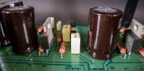
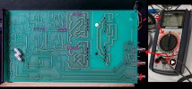
Okay - so don't laugh but my first attempt at getting these readings was a joke. Not sure if these numbers even make sense as I wasn't even sure what multimeter setting to use and whether to use the red or black plug on the RCA shields but hey I did get some readings at least ;-) I guess I better google me some beginner lessons. Cheers!Measure the voltages (opposite signal ground which is the RCA shields for instance) on points A, B, C and D and post the results here... for starters.
View attachment 323226
Then we know what the power supply does and does not do and where to measure next.
")
Okay so I've now tested a battery as suggested and it reads as 9 volt (so we know the DMM is workingblack lead on the RCA shield.
red lead on each measurement points.
Set the multimeter on 200 V DC setting (arrow points to the correct setting).
Check the operation of the voltmeter first on a battery (1.5V or 9V) to see if what the meter shows is a correct value.
Also check the 20V DC setting on those batteries.
When that test goes well (gives expected values)
I would expect to see around + 21 to +25V on A (measure on 200V DC setting)
I would expect to see around - 21 to -25V on B (measure on 200V DC setting)
I would expect to see around - 15 to -17V on C (measure on 20V DC setting)
I would expect to see around + 15 to +17V on D (measure on 20V DC setting)
The numbers you got make no sense.
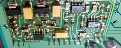
The voltage regulators are LM317 (positive regulator) and LM337 (negative regulator)
Opamps were used to set the output voltages on the regulators instead of the usual 2 resistor design and most likely to check if both the power rail voltages are present to ensure a correct on/off operation and PS fault detection (as there is no output relay).
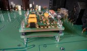
Given the fact that this is already a difficult thing to do I would suggest to not work on the amplifier PCB's.
This requires expert knowledge when working without schematics as there is also a crossfeed circuit on those amplifier PCBs.
But before anything see if the DC voltages check out.
Unfortunately the PCB readings don't look as promising as this is what they are : A=00.1 (200V)New photo of the voltage regulator part number as requested (info sheet link below).
https://www.ti.com/lit/ds/symlink/lm336-2.5.pdf?ts=1698953511441&ref_url=https%3A%2F%2Fwww.ti.com%2Fproduct%2FLM336-2.5
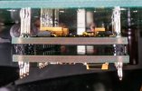
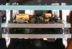
Added underside pics of the tiny amplifier PCB board just for fun . Still working on my first measurement readings (once I figure out exactly how to do them ;-)
I guess this is a sign of a broken output transistor, the silicon chips inside the transistor have "evaporated" through the encapsulation.I had a closer look and yes that dark spot is there but it looks more like a pyramid sitting on top as opposed to a crater (?)