It's not completely clear to me how that PWB assembly is fastened to the main board, but it does appear the staked through hole pins are soldered on the component (top) side. Do not Dremel anything! If you're not familiar with soldering, don't go there either. Do the best you can with iso and a brush and see where that gets you.

-
WANTED: Happy members who like to discuss audio and other topics related to our interest. Desire to learn and share knowledge of science required. There are many reviews of audio hardware and expert members to help answer your questions. Click here to have your audio equipment measured for free!
You are using an out of date browser. It may not display this or other websites correctly.
You should upgrade or use an alternative browser.
You should upgrade or use an alternative browser.
HEADROOM Headphone Amp repair help :)
- Thread starter JazKazman
- Start date
Oh, and make sure you thoroughly dry the thing after the cleaning. 91% is still 9% water, 99% is better, but harder to get. Use a hair dryer or equivalent, then when it's toasty and dry, let it sit overnight before applying power again.
solderdude
Grand Contributor
On the other side there is a copy of the upper PCB for the other channel.
Remove the small PCBs, which is the actual amplifier (not going to be easy when inexperienced).
Chances are the bottom board may have gotten even hotter as there is no ventilation there.
The right output transistor seems to have been really hot as both the tab and the collector seems to have almost unsoldererd itself.
The main PCB is double layer so means there are vias in the pads making them hard to unsolder, even with soderwick.
If it were mine I would probably cut the pins below the bottom PCB (going to the main PCB) and remove the amplifier board.
Remove what's left of the pins one by one. Clean out the pads on the main board.
Check if there is a +/- power supply going to the middle pins where the board was.
There probably should be + and - 17V (or something close to it)
Then try to find a schematic for the amp boards or try to fix it (needs an experienced repairguy).
Judging from the question which meter to use I would guess that may not be you and suspect something is wrong on the amp board (output transistor blown I reckon)
Last edited:
solderdude
Grand Contributor
I don't think you will be able to solder out the amplifier boards completely with the pins intact. I bet I couldn't even do that.
Removing solder from the pads may well be possible but not the solder in the through holes.
You could pull out the throughs and sometimes signals have to go through them.
In that case new pins (on the amp boards) will have to be soldered on both sides of the main PCB.
I suspect you need to cut each of the pins... carefully... and then grab each pin with a small pliers. Heat the pin so solder melts completely.
GENTLY pull out the remainder of the pins while applying heat.
Once all the pins are out clean out the holes (soderwick or desolder gun) or when you are really adventurous heating the pads and blow out the holes with compressed air (HOT splatters, very dangerous).
Then comes the task of fixing the amp boards and soldering in 2 pins.
Separating the 2 PCB's may not be needed to fix it (suspect it needs fixing) but putting in new pins so it can be mounted on the main PCB again may not be easy.
OP
JazKazman
Member
- Joined
- Oct 26, 2023
- Messages
- 28
- Likes
- 2
- Thread Starter
- #29
My limited experience with soldering has been mostly connecting/repairing wiring in RCA plug cords and such using flux and solder. I have tinkered though with PCB's in the past just haven't desoldered anything (yet ") other than re-heating the existing solder to soften it enough to remove. Man - you guys must be laughing at my newbie-ism
other than re-heating the existing solder to soften it enough to remove. Man - you guys must be laughing at my newbie-ism
I'll start with the cleaning first. I was hoping it was that little bit on the back side I already cleaned.
other than re-heating the existing solder to soften it enough to remove. Man - you guys must be laughing at my newbie-ismI'll start with the cleaning first. I was hoping it was that little bit on the back side I already cleaned.
Just remember, once you cut the pins, you'll need to get new ones and basically re-stake that board, then get it all put back together and resoldered. Plus the components on the little PWB are surface mount. Much trickier than doing thru-hole leads.
I have a powered vacuum de-soldering tool (Hacko) and temp controlled soldering station (Weller) and all the flux and solder. I would be very hesitant to tackle this just from a rework perspective. Never mind the troubleshooting part (and I'd want an oscilloscope for that). But hey, if it's all in fun...
I have a powered vacuum de-soldering tool (Hacko) and temp controlled soldering station (Weller) and all the flux and solder. I would be very hesitant to tackle this just from a rework perspective. Never mind the troubleshooting part (and I'd want an oscilloscope for that). But hey, if it's all in fun...
OP
JazKazman
Member
- Joined
- Oct 26, 2023
- Messages
- 28
- Likes
- 2
- Thread Starter
- #32
>>But hey, if it's all in fun...<<
Yup. Imagine bringing a 100 year old rusty pocketwatch or a WWII wristwatch ticking again after dismantling, cleaning/oiling and putting it all back together again (not that I'm always successful with that hobby but hey, when it comes back to life, ticking once again it is a bit of a thrill). I still even have every stereo I've ever owned including lots of vintage tube gear from the 50's/60's and ancient PCs from the CPM/OS days.... so have always been keen on learning. Cheers all!
Yup. Imagine bringing a 100 year old rusty pocketwatch or a WWII wristwatch ticking again after dismantling, cleaning/oiling and putting it all back together again (not that I'm always successful with that hobby but hey, when it comes back to life, ticking once again it is a bit of a thrill). I still even have every stereo I've ever owned including lots of vintage tube gear from the 50's/60's and ancient PCs from the CPM/OS days.... so have always been keen on learning. Cheers all!
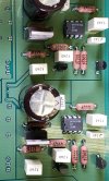
Thank you. It appears that they are possibly using the LM358N OP amps in single voltage supply operation. So there is apparently a voltage regulator beside each of the OP amps. Can you make a pic of those so I can see what they are doing too.>>While you are at that can you please make images of those OP amps so the datasheet can be sourced and then we can look at voltages and determine if they are getting voltage.<<
restorer-john
Grand Contributor
No. Do not remove any flux or residue. The goal is not to make it look pretty for an ASR photoshoot. The goal is to find and repair the fault. Flux is not an issue and never has been in audio electronics. It actually protects the boards and joints.
So, step one (again) is check all your power supply rails with the unit powered up. Whatever the problem is, it's common to both channels and what is common to both channels??
So, step one (again) is check all your power supply rails with the unit powered up. Whatever the problem is, it's common to both channels and what is common to both channels??
Last edited:
This is an aside and going off topic, and not wantin' to get into an argument with ya, restorer, and my 40 years of experience is in military electronics, not audio (unless sonar counts), but any assembler submitting the above PWB for inspection would be in for remediation, if not fired. The following quote is from the Digikey information sheet on solder flux. I'll just leave it there.
"first type, rosin-based flux, is made from pine tree sap and then dissolved in a solvent, usually isopropyl alcohol. The resulting product is slightly acidic, which helps dissolve built-up gunk and oxidization. In this state, the flux is called type-R rosin flux. However, manufacturers can add additional acid activators to make the flux more aggressive and increase its ability to dissolve heavier oxide films, which may be required when soldering at higher temperatures, such as lead-free solder. Depending on the activation level, the flux is categorized into RMA (rosin mildly activated) and RA (rosin activated). Due to its acidic nature, this flux must be cleaned off the PCB after assembly to prevent it from corroding the board over time."
"first type, rosin-based flux, is made from pine tree sap and then dissolved in a solvent, usually isopropyl alcohol. The resulting product is slightly acidic, which helps dissolve built-up gunk and oxidization. In this state, the flux is called type-R rosin flux. However, manufacturers can add additional acid activators to make the flux more aggressive and increase its ability to dissolve heavier oxide films, which may be required when soldering at higher temperatures, such as lead-free solder. Depending on the activation level, the flux is categorized into RMA (rosin mildly activated) and RA (rosin activated). Due to its acidic nature, this flux must be cleaned off the PCB after assembly to prevent it from corroding the board over time."
restorer-john
Grand Contributor
This is an aside and going off topic, and not wantin' to get into an argument with ya, restorer, and my 40 years of experience is in military electronics, not audio (unless sonar counts), but any assembler submitting the above PWB for inspection would be in for remediation, if not fired. The following quote is from the Digikey information sheet on solder flux. I'll just leave it there.
"first type, rosin-based flux, is made from pine tree sap and then dissolved in a solvent, usually isopropyl alcohol. The resulting product is slightly acidic, which helps dissolve built-up gunk and oxidization. In this state, the flux is called type-R rosin flux. However, manufacturers can add additional acid activators to make the flux more aggressive and increase its ability to dissolve heavier oxide films, which may be required when soldering at higher temperatures, such as lead-free solder. Depending on the activation level, the flux is categorized into RMA (rosin mildly activated) and RA (rosin activated). Due to its acidic nature, this flux must be cleaned off the PCB after assembly to prevent it from corroding the board over time."
Here is what I wrote again. I've underlined and bolded the important part for you, so you don't go off track again:
Flux is not an issue and never has been in audio electronics.
We are discussing a handmade domestic headphone amplifier here, not military RF gear. The same rules do not apply.
solderdude
Grand Contributor
Measure the voltages (opposite signal ground which is the RCA shields for instance) on points A, B, C and D and post the results here... for starters.

Then we know what the power supply does and does not do and where to measure next.
Then we know what the power supply does and does not do and where to measure next.
JayGilb
Major Contributor
I would resolder all of the pins in this image. If you have flux, then apply a little to each of the rca connector legs prior to soldering.
Hold the soldering iron for a little longer on the rca connector legs to make sure they are properly heated before adding solder.
While this will probably not fix your problem, those connections should be resoldered.
solderdude
Grand Contributor
No... these connections were severed in the factory.
The main PCB was a universal PCB for various models.
Leave it as it is.
The scratch seems to be on the soldermask only, the trace is not cut otherwise one channel would never have worked.
The main PCB was a universal PCB for various models.
Leave it as it is.
The scratch seems to be on the soldermask only, the trace is not cut otherwise one channel would never have worked
.
Last edited:
JayGilb
Major Contributor
There are better ways to make a PCB universal than this hack method. A couple of trace pads and a few jumper wires come to mind.No... these connections were severed in the factory.
The main PCB was a universal PCB for various models.
Leave it as it is.
Maybe this was an ECO for a incorrectly designed board ?
Similar threads
- Replies
- 5
- Views
- 605
- Replies
- 0
- Views
- 648
- Replies
- 0
- Views
- 204
- Replies
- 23
- Views
- 1K