
-
Welcome to ASR. There are many reviews of audio hardware and expert members to help answer your questions. Click here to have your audio equipment measured for free!
You are using an out of date browser. It may not display this or other websites correctly.
You should upgrade or use an alternative browser.
You should upgrade or use an alternative browser.
For newbies: common mistakes with REW, how to ask for help on ASR
- Thread starter Keith_W
- Start date
How should I do this when measuring left/right channel? Do I need to point each speaker when measuring, rather than pointing at the center of the TV between two speakers?Microphones need to be pointed at the speakers, and not up at the ceiling.
Shouldn't I position the microphone in the exactly same position for both channels (by pointing the microphone to the TV all the time)?
Regarding microphone orientation, it is often better to point it up at the ceiling. This is the case if we are interested in low frequencies, as for instance when EQing down peaks from room modes or integrating subwoofers. Just remember to use the right calibration file.
The REW help pages writes more about this here: https://www.roomeqwizard.com/help/help_en-GB/html/gettingstarted.html#top
Here’s a quote: «For low frequency measurements (below a few hundred Hz) the mic can be set pointing straight up. This avoids having to move it to measure different speakers and makes it easy to read the display on a meter. Use a "90 degree" mic calibration file if pointing the mic upwards. To make measurements at higher frequencies it is best to point the mic directly at the speaker being measured. Use a "0 degree" mic calibration file in that case. In both cases the mic should be placed at ear height in your usual listening position.»
I missed that the OP has a link to an article about microphone.
 www.jochenschulz.me
Doesn't changing the distance from the microphone to the speaker also affect the high frequency response?
Keeping the distance to the two speakers exactly the same while rotating the microphone is not trivial. That could be a reason why Auto-EQ system like Dirac does not instruct the user to point the microphone at each speaker while measuring a point in a room.
Simply rotating the microphone using the boom attached to a microphone stand changes the distance to each speaker.
Which angle is correct for the measuring microphone? — Jochen Schulz
Where do I point my measurement microphone when I measure? Towards the speaker, or toward the ceiling? And does it make any difference with an omni-directional characteristic? Using three measurement microphones (Behringer ECM8000, Beyerdynamic MM1, iSEMcon EMX-7150), I show you in practice what you
www.jochenschulz.me
So it's okay to aim the microphone in the middle of the two speakers as long you understand that it might make some differences in frequency response above 2Khz? But doesn't that make more than "a derivation of a few degrees" difference if the two speakers are set up in an equilateral triangle (or in an isosceles triangle), depending on how far apart they are placed?A deviation of a few degrees has only a minor impact, so that with a stereo setup, we can aim exactly in the middle of the two speakers.
Doesn't changing the distance from the microphone to the speaker also affect the high frequency response?
Keeping the distance to the two speakers exactly the same while rotating the microphone is not trivial. That could be a reason why Auto-EQ system like Dirac does not instruct the user to point the microphone at each speaker while measuring a point in a room.
Simply rotating the microphone using the boom attached to a microphone stand changes the distance to each speaker.
OP
Keith_W
Major Contributor
- Thread Starter
- #25
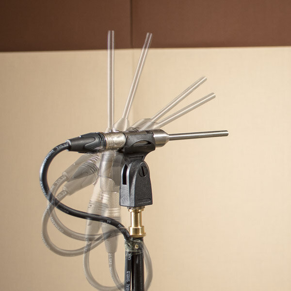
Why you should angle your microphone towards the speaker.

This is the Earthworks M23 microphone polar plot, taken from @SIY review on AudioXpress. Note some features of the polar plot: it is omnidirectional at 1kHz, and it becomes progressively less omni as wavelengths get shorter. Note that if you were to point it at 90deg (towards the ceiling) it would be -5dB at 16kHz. If you point it towards the source, it is completely flat.
Re: your question about isosceles triangles. In this case the direct wave is 30deg off axis towards the microphone which is pointing directly between the two speakers. Look at the polar plot again, and you can see that there is some volume loss at high freqs, but it is minimal, maybe 0.5dB or less.
This is also why there is a different calibration file for 0deg and 90deg.
Re: changing the distance to the speaker. Yes it is true that volume drops off with further distance from the speaker according to the inverse square law. I suppose how much of an impact it makes depends on the geometry of your measurement setup. If the boom rotation radius is large compared to the distance to the speaker (e.g. if you are measuring bookshelf speakers on a table) it might be more significant. But if you are measuring speakers in a listening room and you are a few meters away, the difference would be negligible.
I don't agree with this, because if you point the mic towards the ceiling you would use the 90 degree cal file, which compensates for this. Of course, it may then exaggerate the high frequencies of the sound radiated from the surroundings, but I think the difference is small in most cases.Why you should angle your microphone towards the speaker.
View attachment 408136
This is the Earthworks M23 microphone polar plot, taken from @SIY review on AudioXpress. Note some features of the polar plot: it is omnidirectional at 1kHz, and it becomes progressively less omni as wavelengths get shorter. Note that if you were to point it at 90deg (towards the ceiling) it would be -5dB at 16kHz. If you point it towards the source, it is completely flat.
OP
Keith_W
Major Contributor
- Thread Starter
- #28
I don't agree with this, because if you point the mic towards the ceiling you would use the 90 degree cal file, which compensates for this. Of course, it may then exaggerate the high frequencies of the sound radiated from the surroundings, but I think the difference is small in most cases.
Read further down the post where I suggested using the 90deg calibration file.
OP
Keith_W
Major Contributor
- Thread Starter
- #29
Following a few similar queries on ASR I decided I would update this guide with:
HOW TO USE REW TO ANALYSE ROOM ACOUSTICS
Step 1: Take the measurement
If you have an SPL meter:
1. Use your SPL meter (C-weighting, slow) to measure the room's noise floor. It should be about 40-45dB.
2. Using your SPL meter, calibrate REW's output to 75dB.
3. Take a proper measurement from the main listening position. What is important is REPEATABILITY. Do not take before and after measurements after you move your microphone, for e.g. after installing acoustic foam! Mark the position of the microphone with masking tape if you need to move the mic. Some people use a plumb line.
If you do not have an SPL meter, I have a suggested workaround. The idea is to compare the noise floor of the measurement with a dummy measurement of the room's noise floor. I came up with this method myself so I have no idea what @JohnPM thinks of it.
1. Place your mic at the listening position.
2. Mute your speakers and use REW's MMM recorder. Do not play any sound, let it record the room's ambient noise. After about 20sec, end the measurement and save the recording.
3. We will assume your room's noise floor is 40dB. Using "align SPL" (in All SPL tab, right click on the graph), choose an alignment level of 40dB. Set it aside for now. Now we take the measurement.
4. Take a sweep as per normal.
5. Go to the waterfall and zoom out so that the first 1000ms is displayed. Compare the waterfall of your sweep with the waterfall of the noise you recorded earlier. You want to see if the noise level is the same.
6. If it is louder or softer than the reference noise floor of 40dB, use "align SPL" on the measurement and choose 75dB to start. Compare again until you see the noise floor of the MMM recording and your measurement looks the same. Take note of how much you had to adjust the SPL.
7. Increase/decrease the gain of your measurement volume by the amount noted. Repeat the sweep.
Step 2: Look at the Energy-Time Curve

1. Go to REW's "Impulse" tab. From the drop down menu, change the view from % to dBFS.
2. Hold down the CTRL key and right click and drag to create a box. You want to see the first 30ms of the ETC. Then left click inside the box to zoom. You will see something like this:

3. The first 20ms of the ETC is the Haas Fusion Zone. Reflections that arrive within the first 20ms are integrated with the direct sound. If they are early and loud, the effect is to smear the sound and reduce clarity. After 20-30ms (depending on wavelength) the sound is perceived as ambience or spaciousness. After 50-150ms (again depending on frequency) the sound is perceived as a separate event - an echo. For this reason, very early reflections <20ms should be -15dB to the main impulse. Mentally draw in a line and study any peaks that occur above the line.
4. I have labelled the reflections 1, 2, 3, 4. Taking the first reflection alone, we see that it is -4dB to the main impulse, with a 1.5ms delay. This is very bad.
5. Convert the delay to distance with this formula: d = tc/1000 where d is distance in feet or meters, t is time in milliseconds, and c is the speed of sound (343m/s or 1125ft/s). In this case, 1.5ms is a distance of 0.515m, or 1.78ft.
6. Now go around your listening room with a tape measure to see where the reflection has come from. This is how. Measure the distance from the mic to the speakers, and then measure the distance from the mic/speaker to the suspected boundary which caused the reflection. Then do this calculation:

2x = direct sound, time reference zero.
2y = distance travelled by reflection
d (from energy time curve) = 2y - 2x
If d matches 2y-2x, you have found your culprit. Slap some absorbent foam on it and re-measure.
HOW TO USE REW TO ANALYSE ROOM ACOUSTICS
Step 1: Take the measurement
If you have an SPL meter:
1. Use your SPL meter (C-weighting, slow) to measure the room's noise floor. It should be about 40-45dB.
2. Using your SPL meter, calibrate REW's output to 75dB.
3. Take a proper measurement from the main listening position. What is important is REPEATABILITY. Do not take before and after measurements after you move your microphone, for e.g. after installing acoustic foam! Mark the position of the microphone with masking tape if you need to move the mic. Some people use a plumb line.
If you do not have an SPL meter, I have a suggested workaround. The idea is to compare the noise floor of the measurement with a dummy measurement of the room's noise floor. I came up with this method myself so I have no idea what @JohnPM thinks of it.
1. Place your mic at the listening position.
2. Mute your speakers and use REW's MMM recorder. Do not play any sound, let it record the room's ambient noise. After about 20sec, end the measurement and save the recording.
3. We will assume your room's noise floor is 40dB. Using "align SPL" (in All SPL tab, right click on the graph), choose an alignment level of 40dB. Set it aside for now. Now we take the measurement.
4. Take a sweep as per normal.
5. Go to the waterfall and zoom out so that the first 1000ms is displayed. Compare the waterfall of your sweep with the waterfall of the noise you recorded earlier. You want to see if the noise level is the same.
6. If it is louder or softer than the reference noise floor of 40dB, use "align SPL" on the measurement and choose 75dB to start. Compare again until you see the noise floor of the MMM recording and your measurement looks the same. Take note of how much you had to adjust the SPL.
7. Increase/decrease the gain of your measurement volume by the amount noted. Repeat the sweep.
Step 2: Look at the Energy-Time Curve
1. Go to REW's "Impulse" tab. From the drop down menu, change the view from % to dBFS.
2. Hold down the CTRL key and right click and drag to create a box. You want to see the first 30ms of the ETC. Then left click inside the box to zoom. You will see something like this:
3. The first 20ms of the ETC is the Haas Fusion Zone. Reflections that arrive within the first 20ms are integrated with the direct sound. If they are early and loud, the effect is to smear the sound and reduce clarity. After 20-30ms (depending on wavelength) the sound is perceived as ambience or spaciousness. After 50-150ms (again depending on frequency) the sound is perceived as a separate event - an echo. For this reason, very early reflections <20ms should be -15dB to the main impulse. Mentally draw in a line and study any peaks that occur above the line.
4. I have labelled the reflections 1, 2, 3, 4. Taking the first reflection alone, we see that it is -4dB to the main impulse, with a 1.5ms delay. This is very bad.
5. Convert the delay to distance with this formula: d = tc/1000 where d is distance in feet or meters, t is time in milliseconds, and c is the speed of sound (343m/s or 1125ft/s). In this case, 1.5ms is a distance of 0.515m, or 1.78ft.
6. Now go around your listening room with a tape measure to see where the reflection has come from. This is how. Measure the distance from the mic to the speakers, and then measure the distance from the mic/speaker to the suspected boundary which caused the reflection. Then do this calculation:
2x = direct sound, time reference zero.
2y = distance travelled by reflection
d (from energy time curve) = 2y - 2x
If d matches 2y-2x, you have found your culprit. Slap some absorbent foam on it and re-measure.
OP
Keith_W
Major Contributor
- Thread Starter
- #30
Step 3: Look at the RT60, T30, and T20
Firstly, the RT60 stands for "time for a reverberant field to decay by 60dB after the early decay time (EDT)". Read the REW manual for a more detailed explanation. The requirements to note are:
"Reverberant field". A reverberant field is a multitude of room modes overlaid over each other such that the volume is uniform over the field. All wavelengths form room modes. Short wavelengths form thousands of modes, so form reverberant fields. As wavelengths get longer, the modes start to separate out through the transition zone until we enter the modal zone, where distinct peaks and dips are seen. This is no longer a reverberant field.
"60dB decay". The typical noise floor of a room is 40dB, which means that the measurement needs to be taken at least 100dB to observe a 60dB decay. This is not practical with domestic loudspeakers since they are likely to distort at that volume.
For this reason, we look at the T20 and T30 instead. The "reverberant" requirement is dropped, and the decay to 20dB or 30dB is measured, then extrapolated to 60dB by simple multiplication. For our purpose, T20 and T30 can be used interchangeably with the RT60.
The T20, T30, and RT60 targets vary depending on room volume and application. To my knowledge, REW does not have an RT60 target calculator*. So this is Acourate's:
* I am far from a REW expert, I tend to use Acourate for all my measurement needs. I have a passing knowledge of REW so I might be wrong here. If REW does have an RT60 target calculator, please let me know!

Note the different standards for RT60, specifically DIN 18041 Music and EBU 3276 studio. Also note that Acourate calculates the upper/lower tolerances based on room volume and application. If you do not have an RT60 calculator, ask me nicely and i'll calculate it for you. Or, as a rule of thumb, aim for a target between 250ms - 500ms. Studios need a lower target, usually below 250ms.
All RT60, T20, and T30 measurements below 150Hz (depending on the size of your room and your Schroder frequency) should be ignored. Those are likely to be room modes and not reverberation.
Firstly, the RT60 stands for "time for a reverberant field to decay by 60dB after the early decay time (EDT)". Read the REW manual for a more detailed explanation. The requirements to note are:
"Reverberant field". A reverberant field is a multitude of room modes overlaid over each other such that the volume is uniform over the field. All wavelengths form room modes. Short wavelengths form thousands of modes, so form reverberant fields. As wavelengths get longer, the modes start to separate out through the transition zone until we enter the modal zone, where distinct peaks and dips are seen. This is no longer a reverberant field.
"60dB decay". The typical noise floor of a room is 40dB, which means that the measurement needs to be taken at least 100dB to observe a 60dB decay. This is not practical with domestic loudspeakers since they are likely to distort at that volume.
For this reason, we look at the T20 and T30 instead. The "reverberant" requirement is dropped, and the decay to 20dB or 30dB is measured, then extrapolated to 60dB by simple multiplication. For our purpose, T20 and T30 can be used interchangeably with the RT60.
The T20, T30, and RT60 targets vary depending on room volume and application. To my knowledge, REW does not have an RT60 target calculator*. So this is Acourate's:
* I am far from a REW expert, I tend to use Acourate for all my measurement needs. I have a passing knowledge of REW so I might be wrong here. If REW does have an RT60 target calculator, please let me know!
Note the different standards for RT60, specifically DIN 18041 Music and EBU 3276 studio. Also note that Acourate calculates the upper/lower tolerances based on room volume and application. If you do not have an RT60 calculator, ask me nicely and i'll calculate it for you. Or, as a rule of thumb, aim for a target between 250ms - 500ms. Studios need a lower target, usually below 250ms.
All RT60, T20, and T30 measurements below 150Hz (depending on the size of your room and your Schroder frequency) should be ignored. Those are likely to be room modes and not reverberation.
OP
Keith_W
Major Contributor
- Thread Starter
- #31
Step 4: Look at the waterfall

Waterfall graphs have a tendency to lie to you. So note how I have configured my graph. I have extended the time range to 1000ms and shown the entire measurement from 0dB to max SPL. Once you do this, the noise floor is easily visible as a flat area on the graph. We will take a closer look at two "fingers" which I have labelled and diagnose what they are.

This is finger 2. Note that Finger 2 does not correspond with a peak in the frequency response. Also, the amplitude decays like it fell off a cliff and then suddenly stops falling, and extends into a constant horizontal ridge. Therefore, finger 2 is noise. It centres around 60Hz. Possible culprits include AC power hum, refrigerators, computer fans, air conditioning units, etc.

This is finger 1. Note how it corresponds with a peak and volume drop-off is constant and extends to the 1000ms boundary. Therefore, finger 1 is a room mode.

Once we know where the noise floor is we can adjust the time range to something more sensible (Controls - time range) for a closer look at the waterfall. I chose 400ms because I saw that the noise floor started at about 300ms or so. You can get the same value from looking at the RT60.
Being able to set the noise floor is one of very few uses for an SPL meter in REW. I personally do not think it is worth the purchase given that you can work around it. I own one, but I did not know any better at the time.
Step 5: Look at the other graphs
REW's help pages are very useful. Rather than re-type everything John said, I will link to them instead:
- Spectrogram (note, I prefer to look at the Spectro over the waterfall. The Spectro is better for looking at decay, the waterfall is better to look at the frequency response)
- Clarity
There are other graphs, but these are the main ones that I use.
Waterfall graphs have a tendency to lie to you. So note how I have configured my graph. I have extended the time range to 1000ms and shown the entire measurement from 0dB to max SPL. Once you do this, the noise floor is easily visible as a flat area on the graph. We will take a closer look at two "fingers" which I have labelled and diagnose what they are.
This is finger 2. Note that Finger 2 does not correspond with a peak in the frequency response. Also, the amplitude decays like it fell off a cliff and then suddenly stops falling, and extends into a constant horizontal ridge. Therefore, finger 2 is noise. It centres around 60Hz. Possible culprits include AC power hum, refrigerators, computer fans, air conditioning units, etc.
This is finger 1. Note how it corresponds with a peak and volume drop-off is constant and extends to the 1000ms boundary. Therefore, finger 1 is a room mode.
Once we know where the noise floor is we can adjust the time range to something more sensible (Controls - time range) for a closer look at the waterfall. I chose 400ms because I saw that the noise floor started at about 300ms or so. You can get the same value from looking at the RT60.
Being able to set the noise floor is one of very few uses for an SPL meter in REW. I personally do not think it is worth the purchase given that you can work around it. I own one, but I did not know any better at the time.
Step 5: Look at the other graphs
REW's help pages are very useful. Rather than re-type everything John said, I will link to them instead:
- Spectrogram (note, I prefer to look at the Spectro over the waterfall. The Spectro is better for looking at decay, the waterfall is better to look at the frequency response)
- Clarity
There are other graphs, but these are the main ones that I use.
Thank you again!
Two things to add:
Two things to add:
You don´t have to do that manually. REW can do that for you - just do a right click with the mouse and then measure the distance in the impulse response window. A very nice feature.5. Convert the delay to distance with this formula: d = tc/1000
The " decay fingers" won´t always correspond to peaks in the frequency response. E.g. if you EQ one peak away, there will still be a decay "finger", as decay can´t be EQ´ed. So before EQing I would also try to solve the decaymatter first.his is finger 2. Note that Finger 2 does not correspond with a peak in the frequency response. Also, the amplitude decays like it fell off a cliff and then suddenly stops falling, and extends into a constant horizontal ridge. Therefore, finger 2 is noise.
Could my body also be counted as one of furnitures which affects measurements? Sitting too close to the microphone seems to block reflected sound to some extent and skews the result.6. Moving furniture

Where to sit when conducting room measurements
Newbie here, first post. I'm learning a lot in this forum and quickly becoming an audio objectivist. Thanks! When you're doing room measurements with Dirac or REW or whatever, where do you sit? In the listening position? Long story, small room, I've been sitting just outside the room with...
www.audiosciencereview.com
Near-field room correction measurements: With or without chair? Occupied or not?
I've never seen this question addressed anywhere, so forgive me if it's redundant. I'm trying to determine how my room should be configured when I'm making room correction measurements for my home office setup (in a small room, with speakers positioned for relatively near-field listening). For...
www.audiosciencereview.com
OP
Keith_W
Major Contributor
- Thread Starter
- #34
Could my body also be counted as one of furnitures which affects measurements? Sitting too close to the microphone seems to block reflected sound to some extent and skews the result.
Absolutely. Set REW's timer and exit the room while taking the measurement.
klipschsoundsystem
Member
- Joined
- Sep 9, 2024
- Messages
- 10
- Likes
- 6
guys where do the room modes in my room end? 200hz or 400hz?

holbob
Senior Member
Looks bright corrected, unless you like it that way of course. Target looks like it could be raised 5db.
OP
Keith_W
Major Contributor
- Thread Starter
- #37
guys where do the room modes in my room end? 200hz or 400hz?View attachment 408867
The modal zone is estimated by calculating the Schroder frequency. The formula is:
holbob
Senior Member
OP
Keith_W
Major Contributor
- Thread Starter
- #39
On another note, I made a post in another thread about how to check if you have taken a good measurement: link.
A good measurement has: low noise floor, low distortion, within the loudspeaker's linear range, and reflections arriving late enough to window out. That is, unless it is your intention to actually measure these things. You might want to include bass reflections when doing room correction, for example. And you can decide if you want to correct upper frequencies, although it is better to leave it out. Regardless, your measurement will tell you whether you can use it to answer the question you are asking.
1. REFLECTIONS

This is the energy-time curve with several peaks marked.
The peak marked 1 is low amplitude and barely rise above the decaying sound. It may be noise, it may be a reflection. The way to tell is to repeat the measurement and see if it disappears. Also ask yourself if it makes sense to get reflections that early. Don't forget to account for all surfaces, including the microphone tripod itself.
The peaks marked 2, 3, 4, 5, 6 are most definitely reflections. They rise high above the decaying sound, and the timing makes sense. Some information can be gained from the timing of the reflection. Let's look at 2 - it arrives 4.39ms after the direct sound. Calculating with the speed of sound d = t/1000 * c (t time in ms, c speed of sound 343m/s or 1125ft/s), we obtain a value of 1.51m/4.96ft. If you look around your room with a tape measure, you will find the culprit surface.
This reflection also tells us what the lower limit of our measurement that is reflection-free. The period T is 1/f, so we assume that 4.39ms is the period of one wavelength. Rearranging the equation, we get f = 1000/T (with T in ms). So the lower limit is 228Hz. This means that all frequencies measured below 228Hz are irretrievably contaminated by reflections. All frequencies above can have the reflections windowed out.
2. SIGNAL TO NOISE RATIO

This is the waterfall display with the time range extended to 1000ms. You can easily see the room's noise floor as the flat plain of the graph with the measurement rising above it like a mountain range.
Note the typical noise floor in a living room - it has the appearance of a rising bass response. Living rooms act like low pass filters, drywalls and windows are relatively impermeable to low frequency incursion whilst selectively attenuating high frequencies. The relevant observation is how high the mountain range rises above the plain, not the elevation of the plain itself. An SPL meter is not needed. We can see that our measurement is about 30-35dB above the noise floor, so this measurement gets a “pass”.
3. DISTORTION

Loudspeakers are nonlinear devices. At higher volume, they may have dynamic compression or distortion. We generally want to measure the loudspeaker operating in its linear range. Unless it is our intention to measure "how much" and "when" distortion occurs, of course.
In light brown is the measurement. In dark brown is the noise floor. Below the noise floor, in grey, are distortion components measured by REW. This tells us that the distortion components are below the room noise floor, so the loudspeakers are likely operating within its linear range.
In reality, it is of course possible that speakers are heavily distorting with the distortion components still below the room noise floor (e.g. measuring a computer speaker from 1m away in a noisy environment!). The way to tell is to measure the speaker at different volumes with the help of an SPL meter. At some point, distortion will start to rise sharply. You want to measure below this point.
A good measurement has: low noise floor, low distortion, within the loudspeaker's linear range, and reflections arriving late enough to window out. That is, unless it is your intention to actually measure these things. You might want to include bass reflections when doing room correction, for example. And you can decide if you want to correct upper frequencies, although it is better to leave it out. Regardless, your measurement will tell you whether you can use it to answer the question you are asking.
1. REFLECTIONS
This is the energy-time curve with several peaks marked.
The peak marked 1 is low amplitude and barely rise above the decaying sound. It may be noise, it may be a reflection. The way to tell is to repeat the measurement and see if it disappears. Also ask yourself if it makes sense to get reflections that early. Don't forget to account for all surfaces, including the microphone tripod itself.
The peaks marked 2, 3, 4, 5, 6 are most definitely reflections. They rise high above the decaying sound, and the timing makes sense. Some information can be gained from the timing of the reflection. Let's look at 2 - it arrives 4.39ms after the direct sound. Calculating with the speed of sound d = t/1000 * c (t time in ms, c speed of sound 343m/s or 1125ft/s), we obtain a value of 1.51m/4.96ft. If you look around your room with a tape measure, you will find the culprit surface.
This reflection also tells us what the lower limit of our measurement that is reflection-free. The period T is 1/f, so we assume that 4.39ms is the period of one wavelength. Rearranging the equation, we get f = 1000/T (with T in ms). So the lower limit is 228Hz. This means that all frequencies measured below 228Hz are irretrievably contaminated by reflections. All frequencies above can have the reflections windowed out.
2. SIGNAL TO NOISE RATIO
This is the waterfall display with the time range extended to 1000ms. You can easily see the room's noise floor as the flat plain of the graph with the measurement rising above it like a mountain range.
Note the typical noise floor in a living room - it has the appearance of a rising bass response. Living rooms act like low pass filters, drywalls and windows are relatively impermeable to low frequency incursion whilst selectively attenuating high frequencies. The relevant observation is how high the mountain range rises above the plain, not the elevation of the plain itself. An SPL meter is not needed. We can see that our measurement is about 30-35dB above the noise floor, so this measurement gets a “pass”.
3. DISTORTION
Loudspeakers are nonlinear devices. At higher volume, they may have dynamic compression or distortion. We generally want to measure the loudspeaker operating in its linear range. Unless it is our intention to measure "how much" and "when" distortion occurs, of course.
In light brown is the measurement. In dark brown is the noise floor. Below the noise floor, in grey, are distortion components measured by REW. This tells us that the distortion components are below the room noise floor, so the loudspeakers are likely operating within its linear range.
In reality, it is of course possible that speakers are heavily distorting with the distortion components still below the room noise floor (e.g. measuring a computer speaker from 1m away in a noisy environment!). The way to tell is to measure the speaker at different volumes with the help of an SPL meter. At some point, distortion will start to rise sharply. You want to measure below this point.
Robocop
Member
I disagree with this one. When you listen to music you are in the room so are part of the sound. I setup microphone where my head is and sit beside it.Absolutely. Set REW's timer and exit the room while taking the measurement.
This is a compromise but at least my body is included in the process. Bodies are 70% percent water which is an absorbent. A body would be considered part of the furniture and an influence on the sound. Anything that is present in the listening room has to be considered.
Last edited:
Similar threads
- Replies
- 7
- Views
- 1K
- Replies
- 11
- Views
- 868
- Replies
- 7
- Views
- 492
- Replies
- 4
- Views
- 437
- Replies
- 101
- Views
- 7K