• WANTED: Happy members who like to discuss audio and other topics related to our interest. Desire to learn and share knowledge of science required. There are many reviews of audio hardware and expert members to help answer your questions. Click here to have your audio equipment measured for free!

Focusrite 18i20 (gen.2), Lavry DA10, REW interpretation

HenryL

Member
Joined
Aug 20, 2023
Messages
22
Likes
1
Location
UK
Hello good AS-people,
I've recently been, somewhat belatedly, trying to fill in some of the void of my technical understanding of sampling technology and the gear I'm currently using.
I've read through a load of stuff - much here on ASR now I've discovered it - and currently have indigestion, so seeking some sanity-checking and guidance.

Brief background:
I recently started to use Room EQ Wizard to make some measurements of the frequency response of some outboard gear (a mic preamp) but this led to questions about the behaviour of the ADC and DACs I've been using in my home studio.
I wasn't trying to make noise or distortion measurements of the standalone preamp but rather to check up to as high a frequency as possible for any signs of ringing and to get a general look at the frequency response of the unit, hence I'm coming from that angle.
I wasn't sure at first if I could even realistically use the 18i20 for measurements above 20kHz as not a requirement for an audio interface, and not in the spec, but happily (and slightly surprisedly) found it was not particularly constrained and 192kHz gave a useful measurement range.
However I saw many puzzling things which made me question what was going on, so I ended up measuring the 18i20 interface at a range of sample rates in loopback from an 18i20 line output to a line input, and then using a Lavry DA10 as the output device looped back into the 18i20.

Edit: I mean all of these measurements below were without any additional equipment (mic pre or whatever) between DAC and ADC, just direct connection.

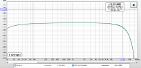
So here's where it started, checking out the FR of the 18i20 itself at 192kHz as a baseline:

18i20 initial 192kHz obs.jpg


The initial low sweep level test (green) at -40dBFS looked pretty horrible at the upper end of the frequency range, then I realised this was a stupid way of generating the low level input for the mic pre I was going to measure...so I changed the sweep level up to -2dBFS and put a hardware pad inline on the output instead to bring it down to the required level. The red 'hi level' above is equivalent to this but using the 18i20 input gain controls to match to the higher output level rather than an external pad. This looked a bit more promising so I made a measurement using a longer sweep length to reduce the noise impact on the FR plot, at high signal level, and used this to generate the REW 'cal' baseline of the interface (to be offset in the further tests of the standalone preamp).

This prompted a few questions for a start:

- The green 'lo' sweep level 'noisyness' looks roughly commensurate with 'hi' red+40dB gain which is consistent at least. But is this amount of mess at the top of the (available/Nyquist) frequency range typical?
- Is this 'noise' (mostly) sampling noise? Thankfully it doesn't appear lower down the spectrum... I'm assuming this is a feature of the converters. I've read a few things now about how they work but so far there's always some point where I get thrown off on a fast bend, or a sudden chasm appears. I'm working on it.

Wondering if it was a random noise effect or a more deterministic phenomenon I ran the maximum (single) sweep length with a low level sweep. This is the blue plot above. IIRC this should reduce noise in the plot by 3dB per doubling, the green is a 1M sweep and the blue is a 4M sweep, so comparing the green with the blue the 'noise' should be about 6dB less.

- The width of the blue mess indeed looks to be about half of the green at first but actually increases disproportionately at higher frequencies - why is it not consistent ? Is there some other factor increasing towards the top of the range?

I keep putting 'noise' in 'quotes' because this is a frequency response plot so we are seeing an effect of noise on the FR measurement rather than noise itself, presumably!? Perhaps not a useful distinction here.

I also wondered a little about the test approach of looping back from an output to an input on the same device. I speculated that on the one hand it should take jitter out of the picture as it is all on the same clock but on the other hand it might be more likely to generate deterministic patterns in the response, or is this nonsense ?

cheers/Henry
 
Last edited:

Blumlein 88

Grand Contributor
Forum Donor
Joined
Feb 23, 2016
Messages
20,771
Likes
37,636
Do note that Lavry devices intentionally roll off above either 30 or 35 khz even at higher sample rates. They don't think you need more than that for human listening.
 
OP
H

HenryL

Member
Joined
Aug 20, 2023
Messages
22
Likes
1
Location
UK
Do note that Lavry devices intentionally roll off above either 30 or 35 khz even at higher sample rates. They don't think you need more than that for human listening.

The Lavry DA10 rolls off from about 2K before Nyquist at 44.1 and 48kHz (ie.from about 20kHz and 22kHz), and 4k before Nyquist at 88.2 and 96kHz (ie. c.40kHz and 44kHz).
The DA10 doesn't go above 96kHz.

Why not just roll off everything from 20kHz steeply enough for the 44.1 case and use it for all higher sample rates too? If it's good enough for the 44.1 case?

The Focusrite behaviour is giving me more pause for thought and seems a bit weird and inconsistent in some aspects. I've read several of your posts touching on the 18i20 performance in more and less detail. I need to sort my own observations/questions and will try to boil them down and post them.

cheers /Henry
 

Blumlein 88

Grand Contributor
Forum Donor
Joined
Feb 23, 2016
Messages
20,771
Likes
37,636
You might also try using white noise at minus 10 db for a test signal. Or letting REW do stepped sines rather than a sweep. You don't need such high FFTs for this purpose either.
 
OP
H

HenryL

Member
Joined
Aug 20, 2023
Messages
22
Likes
1
Location
UK
You might also try using white noise at minus 10 db for a test signal. Or letting REW do stepped sines rather than a sweep. You don't need such high FFTs for this purpose either.
Thanks for the input. Is there a problem with using a sweep? Or what are the advantages of noise or stepped sines?

And for what purpose?

I mean, my original purpose was to test the frequency response of a third piece of kit, not examine the interface/adc/dac per se. But I saw things I wasn't expecting so repeated the same process at other sample rates - for consistency/comparison - to see what the interface was doing there, and now my purpose is to disentangle what those results are telling me. Is there a particular problem hiding in there with the type of information I already have?

(Coincidentally I did have a quick look for a way of measuring the frequency response with noise in REW but the button for this option in the measurement panel was inactive and I didn't spend any more time pursuing it. )
 

Blumlein 88

Grand Contributor
Forum Donor
Joined
Feb 23, 2016
Messages
20,771
Likes
37,636
I've not gotten the results like you are getting with noise in the upper range of results using REW for sweeps. But I am not sure I've done that with a microphone input, maybe just line inputs. I have used REW to test gain and EIN of the microphone input though only using a single tone.

If you use the ADC set to a higher sample rate than the DAC you can see how the filter rolls off above nyquist. You cannot do this with a loopback of the 18i20 as both parts will run at the same rate. You could do it with the Lavry feeding the 18i20. Here is an example though not with the Focusrite.


Stepped sines are more precise though normally sweeps will work just fine. Stepped sines would also help with any noise vs signal issues.

You also might try Pkane's Multitone which has turned into a full measurement suite. I suggest this just to see if you get different results.
 
OP
H

HenryL

Member
Joined
Aug 20, 2023
Messages
22
Likes
1
Location
UK
So here's what I saw running a sweep at 44.1 using an 18i20 output and the LAvry for comparison (the Lavry fed over spdif from the 18i20):

18i20 44.1 hi and lo sweeps lav and foc.jpg


The top two plots are using the 18i20 output 3. I also ran tests using output 8, at the other end of the board, different DAC chip etc. and it was notably less wobbly, though still somewhat, so this behaviour is not consistent across outputs and tends to be there more with lower signal:noise sources. The higher sig:noise sweep (red, top) gets a faster wiggle on. It's only in the tenths-of-a-dB magnitude of FR variation - but it doesn't look great to me.

On the other hand the Lavry lower plots look eminently well-behaved.

What's the expert interpretation of this?

And what's the horrible spike at the end of the sweep? This occurs at the end of all the sweeps I took incl. the Lavry sweep albeit slightly less extreme looking (out of shot above or sometimes lost in the noise as in the earlier post). Is this a normal thing which occurs when you reach the Nyquist freq with a sweep like this?

Sorry for all the Q's.. All help much appreciated.
 
OP
H

HenryL

Member
Joined
Aug 20, 2023
Messages
22
Likes
1
Location
UK
I've not gotten the results like you are getting with noise in the upper range of results using REW for sweeps.
That's interesting to hear. Adds to my feeling it could be something about this method of testing.

But I am not sure I've done that with a microphone input, maybe just line inputs.
My interface loopback tests here are all line output to line input.

If you use the ADC set to a higher sample rate than the DAC you can see how the filter rolls off above nyquist. You cannot do this with a loopback of the 18i20 as both parts will run at the same rate. You could do it with the Lavry feeding the 18i20.
Would have to get another computer up here and another audio interface (as far as I can see), so a bit of a palaver. No laptops to hand unfortunately.
(Edit: oh, ok maybe I just need another interface and could have two interfaces running at different sample rates on the same machine if macos will allow that.)

Thanks for the link. I have read this already once before. But I need to read everything umpteen times it seems before things sink in...

Stepped sines are more precise though normally sweeps will work just fine. Stepped sines would also help with any noise vs signal issues.
Do you mean that they help because each frequency step plays for longer than a passing sweep so the effect of noise on the reading for a given frequency averages out?

You also might try Pkane's Multitone which has turned into a full measurement suite. I suggest this just to see if you get different results.
Thanks for the suggestion. I'm not familiar with it (runs on macos?) will take a look. I'm slightly reluctant to have to learn how to drive another tool already having barely worked out how to do some basic stuff in REW so far! But maybe it will prove necessary :)
Edit: unfortunately it seems to be only for Windows and not mac.
 
Last edited:

Blumlein 88

Grand Contributor
Forum Donor
Joined
Feb 23, 2016
Messages
20,771
Likes
37,636
Been busy so haven't replied. One good thing about Multitone is you can connect multiple USB devices, use drivers or ASIO for each and run them at different sample rates even on a Windows machine.

If anything the biggest issue is Paul's software does so much he needs a big manual to explain everything. But you can likely play with it a bit and get to work for you. Plus Paul and others will help answer your questions. Go to the end of this thread. Paul updates things and adds feature upon request pretty often. OTOH, I'm not sure there is anything it won't do for most purposes by now.


You can download it free here, and he has updated some how to information.
 

AnalogSteph

Major Contributor
Joined
Nov 6, 2018
Messages
3,394
Likes
3,342
Location
.de
The top two plots are using the 18i20 output 3. I also ran tests using output 8, at the other end of the board, different DAC chip etc. and it was notably less wobbly, though still somewhat, so this behaviour is not consistent across outputs and tends to be there more with lower signal:noise sources. The higher sig:noise sweep (red, top) gets a faster wiggle on. It's only in the tenths-of-a-dB magnitude of FR variation - but it doesn't look great to me.

On the other hand the Lavry lower plots look eminently well-behaved.

What's the expert interpretation of this?
Looks like artifact city. Are you sure you didn't have input monitoring turned on?

I am also unaware of REW's sound API limitations on the Mac. You may very well need to keep its sample rate sync'd with system settings. Not sure whether the same limit of 16 bit samples applies when using Java I/O, which is the case on Windows.

Regarding your issue with measurements getting noisy at high frequencies, make sure you're not using the kind of sweep intended for loudspeakers that's dropping off towards the high end. You have no tweeters to be worried about.

Which generation 18i20 is this anyway? Here are some results from what I think is a first-gen. I would expect similar (but better) results from a current model, it's still a CS4272 grave.
 
OP
H

HenryL

Member
Joined
Aug 20, 2023
Messages
22
Likes
1
Location
UK
Thanks for engaging..
Looks like artifact city. Are you sure you didn't have input monitoring turned on?
Not sure what you mean about having input monitoring turned on - could you clarify?

I am also unaware of REW's sound API limitations on the Mac. You may very well need to keep its sample rate sync'd with system settings. Not sure whether the same limit of 16 bit samples applies when using Java I/O, which is the case on Windows.
I've only a superficial knowledge/experience with REW myself but my understanding is that it it is working at 24bit (and I have left the default 'treat 32bit data as 24bit' setting ticked). The sample rates are set consistently through REW, mac view of the interface/device settings and in the Focusrite Control app so I've no concerns there.

Regarding your issue with measurements getting noisy at high frequencies, make sure you're not using the kind of sweep intended for loudspeakers that's dropping off towards the high end. You have no tweeters to be worried about.
Indeed. Again, not to my knowledge! It's sweeping up to 96kHz (in the 192kHz rate measurements) so it is going way out of tweeter zones (though perhaps showing ignorant assumptions about tweeter performance on my part) . But more to the point all the pics I've seen show it to be constant amplitude albeit with a 'soft-start' at the low end.
However this does raise an interesting angle.
Here's a screenshot of an REW sweep from some REW user guide type material (ie.not from my own use):

Screenshot 2023-08-23 at 12.56.07.png


It clearly suggests that it does tail off at the very end. Can't see from this picture over what frequency range it does taper off, but
since generally the S/N gets increasingly worse as the sweep amplitude decreases I'm wondering if this underlies the sudden bloom and spike right at the end of the sweep. Though unless REW was anticipating the tailoff and adjusting for it somehow on the receiving end I would have expected it to just see a reducing signal getting lost in the noise so why the exploding levels at the end of the sweep?

I had been wondering if this might just be a typical effect of approaching the Nyquist limit and/or combined with applying FFT to this.

Anyway it's evidently not tailing off over ~half the sweep range (ref the picture in first post in this thread) so it doesn't explain that, or the ripply regions in the 44.1 trace.

Which generation 18i20 is this anyway?
2nd Gen. (thread title :) )

Here are some results from what I think is a first-gen. I would expect similar (but better) results from a current model, it's still a CS4272 grave.
RightMark Audio Analyzer test : [MME] Ïß·ÊäÈë (2- Scarlett 18i20 USB
I'm assuming it's the same Cirrus chips as the 1st Gen. What do you mean by 'grave' - I've seen this expression used elsewhere but not sure what it is meaning?

The frequency response plots on the linked page look a similar shape to my own 44.1 plots, but hard to see whether it's as wiggly at the 15kHz+ end. The final shape of the response looks similar at the very top, but can't see the gory details at the top. I note it says
20 Hz - 20 kHz filterON


Cheers/ Henry
 
Last edited:

AnalogSteph

Major Contributor
Joined
Nov 6, 2018
Messages
3,394
Likes
3,342
Location
.de
Not sure what you mean about having input monitoring turned on - could you clarify?
Ah, this interface doesn't have a direct monitoring function or monitor mix knob. Rather, you would do input monitoring using custom mixes in Focusrite Control, of which the 18i20 2nd gen supports up to 5. (The front headphone outs are shared with line outputs 7/8 and 9/10, so that's a total of 5 independent output channel pairs then.)
So if in doubt just make sure you don't have any custom mixes set up at all.
Indeed. Again, not to my knowledge! It's sweeping up to 96kHz (in the 192kHz rate measurements) so it is going way out of tweeter zones (though perhaps showing ignorant assumptions about tweeter performance on my part) .
This could be to do with the analysis then - i.e. measurement bandwidth increases as frequency goes up, and so does noise. There's got to be a reason why RMAA uses an MLS type test signal for FR measurements by default instead of a sine sweep (although more recent versions do also offer that).

In any case, the only thing that would cause low-level periodic ripple in the frequency response is a small amount of pre- and/or post-echo, with ripple frequency indicative of time offset.

The only other thing I might suspect is something to do with windowing. Unfortunately I have far too little experience using REW for soundcard loopback measurements.
I'm assuming it's the same Cirrus chips as the 1st Gen. What do you mean by 'grave' - I've seen this expression used elsewhere but not sure what it is meaning?
It just means that there's a bunch of 'em buried in there. :)

In this case that would seem to be no less than four CS4272s, with the 5th output channel pair on behalf of a CS4392 DAC that's a close match. (BTW, did you know that these parts have been out for 20 and 22 years, respectively? And they're still ubiquitous in audio interfaces to this day and well and alive as a product. Not a bad run, I say!)
I note it says
20 Hz - 20 kHz filterON
This is just for distortion and noise figures displayed, I believe.
 
OP
H

HenryL

Member
Joined
Aug 20, 2023
Messages
22
Likes
1
Location
UK
So if in doubt just make sure you don't have any custom mixes set up at all.
I see what you mean. I do use custom mixes but not selected on the outputs (8 & 3) used in these tests.

BTW I think I was wrong about REW working at 24bit in spite of the appearances of '24bit' at various points in the GUI - I saw another snippet in the user guides saying it worked at 16bit.

This could be to do with the analysis then - i.e. measurement bandwidth increases as frequency goes up, and so does noise. There's got to be a reason why RMAA uses an MLS type test signal for FR measurements by default instead of a sine sweep (although more recent versions do also offer that).
I'm presuming MLS means Maximum Length Sequence, at which point I fall off due to lack of knowledge of convolution etc.etc...!

It just means that there's a bunch of 'em buried in there.
dohhh :)

In this case that would seem to be no less than four CS4272s, with the 5th output channel pair on behalf of a CS4392 DAC that's a close match.
That's my assumption based on a Gen.1 teardown I came across.

(BTW, did you know that these parts have been out for 20 and 22 years, respectively? And they're still ubiquitous in audio interfaces to this day and well and alive as a product. Not a bad run, I say!)
I've been browsing around your web site a little - with interest and enjoyment - and I saw that from your ADC/DAC history tables. As you say: not bad going!

In any case, the only thing that would cause low-level periodic ripple in the frequency response is a small amount of pre- and/or post-echo, with ripple frequency indicative of time offset
I noticed (also on your website) you refer to ripples arising from filtering (I'm assuming this is some digital filtering done in the delta-sigma process somewhere) - is that the same thing you are referring to above? I've started noticing the term 'passband ripple' in several places now I'm looking - is that the same thing?

An aspect of this that puzzled me, and gave me a headache, was how inconsistent it seemed to be. I mean mostly the ripples appeared in the low level -40dBFS sine sweep and not in the high level one at -2, but the example I included above for 44.1kHz shows they can occur in the high level sweep too, and then the further puzzle as to why the ripple periods are different at different sweep levels whereas intuitively I would have expected just differences in magnitude if it was some artifact from the DAC processing being amplified. Also surprised how far down the frequency range it extended at times. (The lavry also brought forth some slight rippling in low level sweeps but much gentler).

Why is there no filter rolloff visible on either DAC output or the ADC input in the 18i20 ? Or is it just that the filtering is so steep it is indistinguishable from hitting a brick wall when it is done digitally after massively oversampling (if my vague grip on delta-sigma conversion isn't too wrong). The top ends of the FR plots looks pretty horrible to me. If it's not just an artifact of the measurement process then I'm not sure I'd want it hitting the downstream analogue world even if it's above 20kHz :)

Why don't audio interfaces just filter out at the 20kHz level on the way in and the way out? Ok analogue-ly it is not so easy perhaps for the 44.1kHz case, or 48 even, so they might want to avoid that, but if the digital filtering is so powerful why allow higher frequencies through at all at higher sampling rates? Wouldn't it be better to kill everything above, say, 22kHz (making some concession to bats etc.)?

It was useful to me that the 18i20 enabled me to make some measurements above 20kHz but I didn't expect it to!

Cheers/ Henry
 

AnalogSteph

Major Contributor
Joined
Nov 6, 2018
Messages
3,394
Likes
3,342
Location
.de
I noticed (also on your website) you refer to ripples arising from filtering (I'm assuming this is some digital filtering done in the delta-sigma process somewhere) - is that the same thing you are referring to above? I've started noticing the term 'passband ripple' in several places now I'm looking - is that the same thing?
Sort of related. This is really going into the nitty-gritty of digital filter design now. If you search for "equiripple filter" you'll be swamped with results.
Design of FIR filters
Passband ripple vs. time domain, as explained by the late Julian Dunn
An aspect of this that puzzled me, and gave me a headache, was how inconsistent it seemed to be.
Which is why I suspect it's some sort of windowing-related artifact, with part of the recording randomly getting cut off or something. @JohnPM as the REW author may be able to illuminate matters.
Why is there no filter rolloff visible on either DAC output or the ADC input in the 18i20 ?
Not sure. You can find reasonably detailed DAC and ADC filter responses in the CS4272 datasheet, this is what you should be able to expect (plus a bit of much less steep analog lowpass filtering).
Why don't audio interfaces just filter out at the 20kHz level on the way in and the way out? Ok analogue-ly it is not so easy perhaps for the 44.1kHz case, or 48 even, so they might want to avoid that, but if the digital filtering is so powerful why allow higher frequencies through at all at higher sampling rates? Wouldn't it be better to kill everything above, say, 22kHz (making some concession to bats etc.)?
It's a matter of economics. The anti-alias filters in ADC and interpolation filters in DACs are generally implemented as half-band filters to minimize the number of delay elements (which increase filter latency) and filter coefficients (which take up die space). On the DAC side, this still tends to look much like in the NPC SM5841 filter of yore:
sm5841ab_block.png

So they are doubling sample rate and then apply a half-band filter to it several times. (In an ADC it's essentially the same but backwards.) As you can see, the filters get progressively less complex as requirements ease, and the following interpolation to 64fs/128fs/256fs in delta-sigma DACs tends to be quite basic. This is what you get at the end:
sm5841ab_8x_resp.png


As you can see, any following filtering needs to only transition from passband to stopband at a fairly leisurely pace, between 0.5fs and 7.5fs (almost 4 octaves). This is why oversampling started to get used in the first place. Early non-oversampling DACs would have incredibly complex analog reconstruction filters, think 14th-order Bessel filter modules. Phase response anywhere near fs/2 was terrible, filtering still wasn't all that great, and the things weren't cheap to make - absolutely terrible for any consumer product. So the guys at Philips coming up with oversampling was a pretty genius move... at 4X the analog filter requirements were much reduced, and it turned their existing 14-bit DACs into an effective 15 bits, with a bit of noise shaping on top getting performance into 16-bit terrain in the audio band as desired for CD reproduction. (See SAA7030 datasheet. Nobody would want to be seen with +/-0.2 dB worth of periodic passband ripple these days, but this was 40 years ago. And they didn't have any issues with intersample-overs either unlike a bunch of later designs, but that's another story.)

Most of what you see around fs/2 is dominated by the first filter stage. Now half-band filters tend to have one defining characteristic: They are at an amplitude of 0.5 (6 dB down) at fs/2, come rain, shine or snow. So a filter like this will never be truly non-aliasing, as your stopband rejection will generally be much greater than 6 dB. There's always that transition region between fs/2 and stopband where aliasing can leak out.

Now on the DAC side you tend to take advantage of the fact that there is precious little going on at or near 20 kHz to begin with. If your signal components stop at 20 kHz, at fs = 44.1 kHz the filter has until 22.05 kHz + (22.05 kHz - 20 kHz) = 24.1 kHz to reach its stopband. In filter terms, the transition must occur between 0.453fs (= 20 kHz / 44.1 kHz) and 0.546fs (= 24.1 kHz / 44.1 kHz). And that's exactly what our trusty SM5841 is shooting for:
sm5841ab_8x_pass.png
sm5841ab_8x_trans.png
(In practice, the low signal levels even close to 20 kHz mean that you can get away with even looser characteristics, which is often done to improve upon other more important performance aspects like passband ripple.)

Likewise, on the ADC side, you can just declare that you don't care about anything past 20 kHz and can accept some aliasing should there be anything up there anyway. Now ADC filters that can get to stopband until 24.1 kHz at fs= 44.1 kHz are relatively rare and tend to come with substantial latency (generally 30-40/fs (*)), and for most ADCs operation at 48 kHz is more advised, where you only need to reach stopband by 28 kHz, or a transition between 0.416fs and 0.583fs. Your CS4272, for example, is going for 0.47fs to 0.58fs at single speed.
(Only a handful of mid-high-grade ADCs from the early-mid 2000s are truly - at least approximately - "44.1-kHz-proof". Think AK5394A, AK5385, PCM4220/2, PCM4202/4, CS5396. There's also the special case of the CS5397 with a non-aliasing filter for measurement applications, 0.3958fs to 0.4979fs transition. 0.3958fs is only 17.45 kHz at 44.1 kHz or 19 kHz at 48 kHz though, so maybe not the last word for audio recording...)

At higher sample rates, requirements obviously get even looser, so the CS4272 ADC is going for a 0.45fs passband and 0.68fs stopband at double speed (aliasing-free up to 30.72 kHz at fs = 96 kHz) and 0.24fs / 0.78fs at quad speed (aliasing-free up to 42.24 kHz at fs = 192 kHz) as filter stages drop away. It's obviously not exactly measurement-grade but should cover DACs up to 88.2 kHz or so even in that application. (It is common to just omit part of the filter chain at higher sample rates, though in more modern parts this may only occur past 96 kHz. The current ESS ADCs will drag the entire chain with them up to 192 kHz. It will make the chip run hotter, obviously.)

*) Imagine you're doing live monitoring through an A/D-Processing-D/A chain, where for a vocalist <5 ms of total latency is recommended. Something like 39fs at 44.1 kHz is almost a full millisecond in itself. It goes without saying that nobody is using 44.1 kHz in such an application any more (in the pro space, 48 kHz would be the minimum anyway, and basically no modern audio interface can't do at least 96 kHz, if not 192).
 
Last edited:

Blumlein 88

Grand Contributor
Forum Donor
Joined
Feb 23, 2016
Messages
20,771
Likes
37,636
Had time to pull out my 18i20. 1st gen only goes to 96 khz, but this is the result. No noise issues. This is the regular measuring sweep at 256k FFT. Monitor out to line input.
1693104335729.png


This is a 4 meg FFT sweep.
1693104714896.png
 

Attachments

  • 1693104544120.png
    1693104544120.png
    148.5 KB · Views: 47
Last edited:
OP
H

HenryL

Member
Joined
Aug 20, 2023
Messages
22
Likes
1
Location
UK
Thanks both for taking the time to help with this. Very much appreciated.

@AnalogSteph that's a great explanation, well targeted - and very helpful to me in building bridges between my disparate islands (small rocks... ? :) ) of understanding!

@Blumlein 88 - good to get my sanity checked..! What levels were you using here? I did get plots like this myself too - most of the time when using a higher sweep level in fact (although 192kHz was never as good looking as the lower rates). I posted the red plot above because it was an unusual example where there was conspicuous wiggling even with the -2dBFS sweep level, whereas mostly the 'hi level' sweeps looked pretty smooth.

The noise/wiggling behaviour is associated with the dac/outputs not the adc/inputs as I'm reading it, so a high level sweep (in dBFS terms) will generally give a good looking result like yours above but a low level one (at -40dBFS in my experiments), requiring therefore ~40dB more gain to be applied at the input, brought up the wigglyness as well as the expected increase in random noise fuzz.

(It is common to just omit part of the filter chain at higher sample rates, though in more modern parts this may only occur past 96 kHz.
( Intrigued as to whether this might account for the somewhat wilder behaviour the 192kHz sweeps seemed to exhibit )

Cheers/ Henry
 

Blumlein 88

Grand Contributor
Forum Donor
Joined
Feb 23, 2016
Messages
20,771
Likes
37,636
I used -12 dbFS and then -3 dbFS seeing no real difference. I didn't try -40 db though I could do so.
 

Blumlein 88

Grand Contributor
Forum Donor
Joined
Feb 23, 2016
Messages
20,771
Likes
37,636
Okay line in from monitor out. -57 dbFS or so. Looks more like your plots.
1693138100240.png
 
Top Bottom